Tag: Cisco

Spin up Cisco CSR 1000v in VMware Fusion in 5 Minutes

I have been using the Cisco CSR 1000v as a default gateway in my home lab and I run an IPSec tunnel & LISP between it and my cloud provider (more on LISP in a separate post). The CSR 1000v runs on VMware ESXi, Microsoft Hyper-V, and Amazon Xen hypervisors but it can also run on a laptop/desktop hypervisor like VirtualBox or VMWare Fusion for testing or training purposes.

In this post I will show how to spin up a CSR 1000v instance in VMware Fusion for Mac.


Requirements:

1) I’m running VMWare Fusion 6.0 Professional but you can also run this virtual router on Fusion 4 or 5. I highly recommend using Fusion 5 Professional or 6 Professional if you want to create additional networks and assign the CSR 1000v interfaces to those networks. The feature to add additional networks (similar to Network Editor in VMWare Workstation) was added by VMWare in Fusion 5 Professional and it’s not available in the standard edition of Fusion. Alternatively if you don’t want to pay the extra bucks for the Professional edition, you can use this free tool from Nick Weaver to create the networks if you are running the standard edition. Nick’s tool isn’t the best but it does the job.

2) Go to Cisco and download the latest and greatest software version of the CSR 1000v. The CSR runs Cisco IOS XE and you need to download the OVA package for the deployment.

 
Installation:

The installation process is simple and quick:

1- Launch Fusion and go to File -> New from the top bar menu

2- Once the Installation wizard starts click on More options.  Select Install an existing virtual machine and click Continue.

3- On the next screen click Choose File. Navigate to the folder containing the OVA package, select the file, and click Open and then Continue.

4-  The next window will ask you to save the VM name, choose a name and click Save.

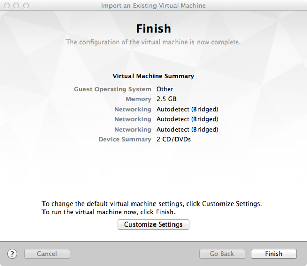
5- The final step of the wizard is to either customize or click fire up the VM. The CSR 1000v by default comes with three interfaces. If you need to add more interfaces click on Customize, otherwise click Finish.

Finish

 
6- Once you click Finish, the CSR 1000v will boot a couple of times and then you will be in traditional Cisco router User Mode.

 
Interfaces Management:

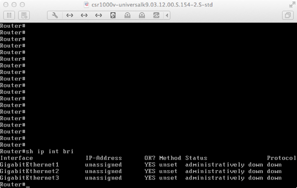
Enter Exec mode and enter “show ip int bri” to see the three interfaces. 

CSR interfaces


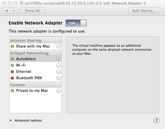
By default interfaces will become part of the Ethernet or WiFi network (that’s done by Fusion) depending on which adapter is active during the installation and you can assign from here IP interfaces and default gateway.

Adapter setting


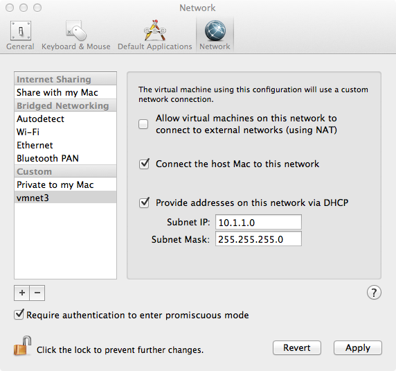
If you wish to put the interfaces on separate networks (VLANs), select the CSR VM and go to Virtual Machine -> Setting and choose the desired Network Adapter. You may also create custom networks by going to VMWare Fusion -> Preferences -> Network. From there add the + sign to add additional network and choose wether to enable DHCP or not.  

Add network


Activating The License

In order to enable the full features of the CSR 1000v, you need to purchase a license from Cisco. If you want to try the full features before purchasing, Cisco offers 60 day free trial license. To activate the free trial license, go into the router configuration mode and enter: license boot level premium. You will be asked to boot the router after you enter the command.   


Share This:
Facebooktwitterredditpinterestlinkedintumblrmail

Using Cisco CSR 1000v As Secure VPN Gateway To Extend Network To The Cloud

Cisco Services Cloud Router (CSR) 1000v is a virtual router you can deploy either in private/public cloud or in a virtualized data center.

One of the common use cases for the CSR 1000v is a secure VPN gateway in the cloud to terminate VPN tunnels. So if you run some applications in the cloud and you want to allow your branch offices to access those application over a secure network, you can run IPsec tunnels between those branch offices and the CSR 1000v in the cloud. From performance perspective this would work much better than back hauling the traffic to the data center (HQ) and then to the cloud.

In this post I will show you how to set up a VPN tunnel between Cisco CSR 1000v and a branch office router using Cisco Easy VPN. You may also use standard IPSec VPN but in my configurations I use Easy VPN because it’s, well, easier 🙂

The following configurations are part of a demo I gave at Cisco Live 2013 in Orlando where the CSR 1000v was the VPN server and the branch server (Cisco 2900 in this case) was the VPN client.

If you would like to learn how to install the CSR 1000v on Verizon Terremark eCloud, follow these steps in my post.

You will also need to open UDP port 500 and IP protocol ID 50 (ESP) on all firewalls sitting between the CSR 1000v and the branch router for the IPSec tunnel to be established successfully. Additionally depending on your design you may need to configure NAT.

In my setup, I’m using:

  • Cisco CSR 1000v with IOS XE 3.9x running in Verizon Terremark Enterprise Cloud
  • Cisco 2900 running IOS 153.2.T (branch office)

Here are the configs of the CSR 1000v (VPN Server). Only relevant configs are shown:

CSR-1#sh run
hostname CSR-1
!
aaa new-model
!
!
aaa authentication login hw-client-groupname local
aaa authorization network hw-client-groupname local
!
!
aaa session-id common
!
!
username myusername password 0 mypassword
!
!
crypto isakmp policy 1
encr 3des
authentication pre-share
group 2
crypto isakmp client configuration address-pool local dynpool
!
crypto isakmp client configuration group hw-client-groupname
key hw-client-password
dns 8.8.8.8
domain domain.com
pool dynpool
save-password
!
!
crypto ipsec transform-set transform-1 esp-3des esp-sha-hmac
mode tunnel
!
!
!
crypto dynamic-map dynmap 1
set transform-set transform-1
reverse-route
!
!
crypto map dynmap client authentication list hw-client-groupname
crypto map dynmap isakmp authorization list hw-client-groupname
crypto map dynmap client configuration address respond
crypto map dynmap 1 ipsec-isakmp dynamic dynmap
!
!
!
interface GigabitEthernet2
description WAN
ip address 10.22.36.71 255.255.255.224
negotiation auto
crypto map dynmap
!
interface GigabitEthernet3
description LAN
ip address 10.22.39.91 255.255.255.240
negotiation auto
!
ip local pool dynpool 192.168.1.1
!
!
ip access-list extended split_t
permit ip 10.22.39.0 0.0.0.255 any
!
end

Here are the configs for the Cisco 2900 router (VPN client).


no aaa new-model
!
ip cef
!
!
username vpntest password 0 vpntest
!
!
crypto ipsec client ezvpn hw-client
connect auto
group hw-client-groupname key hw-client-password
mode client
peer 10.22.36.71
username myusername password mypassword
xauth userid mode local
!
!
interface GigabitEthernet0/0
description WAN
ip address 10.35.120.104 255.255.255.0
duplex auto
speed auto
crypto ipsec client ezvpn hw-client
!
interface GigabitEthernet0/1
description LAN
ip address 172.16.4.102 255.255.255.0
duplex auto
speed auto
crypto ipsec client ezvpn hw-client inside
!
ip route 0.0.0.0 0.0.0.0 10.35.120.1
!
end 

Note: You can also install the CSR 1000v as a VM in VMware Fusion or Oracle VirtualBox if you want to play.


Share This:
Facebooktwitterredditpinterestlinkedintumblrmail

How to Deploy Cisco Cloud Services Router (CSR) 1000v on Verizon Terremark Cloud

Note: This post is obselete. There is easier way now to install the Cisco CSR 1000v on Verizon Cloud. This link describes how to quickly spin up an instance.


The Cisco Cloud Services Router (CSR) 1000v is Cisco’s first virtual router and it runs as a VM on x86 virtualized server. The CSR 1000v runs Cisco IOS XE and brings many benefits to a cloud environment where it can operate as a secure VPN gateway to terminate site-to-site IPSEC tunnels. Other use cases of the CSR 1000v include MPLS WAN termination and control & traffic redirection. You can find more information n this virtual router on the Cisco CSR 1000v page.


In this post I’m going to show you how to install the CSR 1000v on the Verizon Terremark eCloud. If you are not familiar with the Verizon Terremark cloud console, you can go here for some video tutorials.


Download A Free Trial Image

  •  Go to the Cisco Download Center and log in using your Cisco credential. Select the latest software release from the left pane and then download the .iso package from the right pane to your desktop. Don’t download the OVA or BIN packages. This free trial should be good up to 6 months.  

Cisco CSR download

  • You can purchase a license from Cisco and upgrade to a full version after you install the CSR.

Create the VM


  • Go over to the Verizon Terremark Enterprise Cloud (eClould) page and log in using your credential.
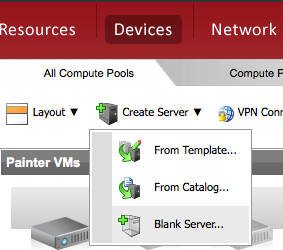
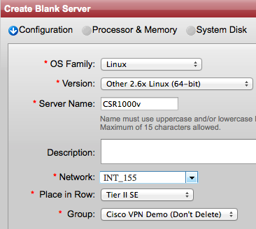
  • The first step here is to create a blank server. A blank server is just a container inside the VMware environment that will hold the Cisco IOS later. So go to Devices -> Create Server -> Blank Server to launch the wizard. 

Create Blank Server

  • On the next screen select Linux for the OS Family, Other 2.6x Linux (64-bit) for the Version. Give the server a name and a description (optional). Then choose an INT network and  choose in which Row and Group you want to place the router. 

 Create blank server

  • On the next screen choose 4 or more for the Processors and 4096 MB or more for Memory. 

Choose VCPU and Memory

  • On the next screen enter 8 for the Disk size or choose a Detached Disk that’s at least 8GB. Click Next.
  • From the next window you can optionally assign tags or just click Next if you don’t want any tag.
  • On the next window review your configurations, check the Agreement box, and click Deploy. Give it about 2 minutes and the server should be ready. If you go to the row and group where you placed the router you should see a greyed out icon (powered off) there. 
  • If you recall we attached only one network to the server earlier, however the CSR requires a minimum of 3 interfaces to run so next we are going to create two additional networks and attach them to the blank server. Right click on the server and go to Configure to launch the wizard.
  • On the next screen choose Configure the Server and click Next.
  • On the next screen click on Network Settings from the top. At this point you should see only one INT network under the Current Connection. Click Add a Connection from the top right to add a new DMZ Network
  • Go click again on Add a Connection and this time choose an INT network (INT_XXX). Choose a unique INT network different from the one you have used when you created the blank server. Click Save.

Create additional vNICs

Now the VM will take a minute or so to reconfigure itself. 

  • Once the wheel stops spinning and VM is ready, right click on it and go to Power On. Powering on this VM should take a minute or so and while the machine is powering on an icon with gear spinning is presented. The greyed out icon should turn into an icon with “blue light” once the server is completely powered on.
 
Console to the VM
 
In order to console to the blank server you must VPN first and use the VMware remote console plugin in Firefox or Internet Explorer to connect to the server for the first time. So for the following steps make sure you are using either Firefox or IE. Once the CSR is up and running you can switch back to your favorite browser or use a Telnet/SSH client to connect it directly instead of using the console.
 
  • Click on the VPN Connect link from the top of the page. This will install the Cisco AnyConnect Mobility Client on your machine if you don’t already have it and connect you via secure SSL VPN to eClould. If the browser prompts you to install any Java or ActiveX plugin during this step make sure to accept. 

VPN Connect

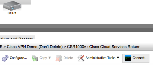
  • Now click on the router icon and then click on Connect from the bottom pane. This will start installing the VMware remote console plugin if it’s not already installed on your machine and will connect you to the server console to install the CSR. Console Connect
  • By now you should see “Operating system not found” message on the console screen. Go to Devices-> CD/DVD drive -> Connect to Disk Image File ISO. This will open a new window for you to locate the ISO package.  Cisco CSR connect to ISO3 
  • Select the ISO package from your local machine and click OK. The system will start uncompressing/unzipping the package and installing software. Depending on the file size and your network speed this process may take up to 2 or 3 hours. Come back in 3 hours to check on the install process. If the console session times out, reconnect again as you did previously.
  •  Once the CSR is successfully installed, you should see the traditional Cisco router prompt and you can then log in and start configuring it. 
Assigning IP Addresses
 
In this section we will assign IP addresses to the CSR 1000v interfaces. When we created the VM we added 3 interfaces for the CSR 1000v to use (INT_XXX, DMZ_XXX, and INT_XXX). Each CSR interface will map to a logical vNIC assigned by the VMware hypervisor. The vNIC in turn is mapped to a physical MAC address.
 
The following steps are very important and you should not begin configuring any features on the CSR 1000v before you execute all of them.
 
  • First we need to find the CSR interface to vNIC mappings so go ahead and create the following table on a piece of paper. You will be populating its fields along the way:
    NIC IDNetworkMACCSR InterfaceIP/MaskDefault Gateway
    1 (eth0)INT
    2 (eth1)DMZ
    3 (eth2)INT
  • Log in to the CSR console and issue the following command:

    show platform software vnic-if interface-mapping

    Csr in mapping
    You should see three interfaces with their vNIC and MAC addresses mapping. If you are running IOS XE 3.10S or earlier the first interface from the top should be GigabitEthernet0 and it’s the management interface. On the other hand if you are running 3.11S or higher the first interface is usually GigabitEthernet1. Start populating the table you have created n the previous step with the information from the command you just executed (IP information will come in the next steps) .

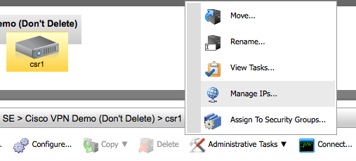
  • Go back to the eClould portal, click on the router and go then to Administrative Tasks -> Manage PIs
    Manage IPs
  • From the Networks section, click on the drop-down menu and select your DMZ network. Then from the left pane Available IPs select one IP address and click on the right green arrow to assign it to the server. Click Save.
  • Repeat the previous step to assign IP addresses for the INT (internal) interfaces.
  • Go back to the table and fill out the IP addresses, mask, gateway sections before you move on.
  • Now that you have the IP addresses, masks, and interface mappings start configuring the DMZ and INT interfaces of the CSR by issuing the following commands for each interface:

    config t
    int gX
    ip add <ip> <mask>
    description <Outside or LAN interface> 

Configure A Default Route
 
  • The final step here is to assign a default route so that the CSR can reach the internet. The CSR must use the DMZ default gateway to reach the internet because only the DMZ network can reach the internet because the INT networks are not visible from the outside. So copy from the table you have created the default gateway IP address for the DMZ network.
  • Go back to the CSR console and issue the following commands. Make sure that you replace the text in italic with the IP address of the default gateway
          config t
          ip route 0.0.0.0 0.0.0.0 <DMZ_Default_gateway>
          end
          write mem 
 
  • Try now pining the default gateway, you should get a response:
          ping <DMZ_default_gateway>
 
  • At this point, the CSR should be able to reach the internet. Issue the following ping to make sure:

    ping 8.8.8.8

    If you don’t get a response then something is wrong and you should revisit the previous steps.


Share This:
Facebooktwitterredditpinterestlinkedintumblrmail

Private VLAN and How It Affects Virtual Machine Communication

Private VLAN (PVLAN) is a security feature which has been available for quite some time on most modern switches. It adds a layer of security and enables network admins to restrict communication between servers in the same network segment (VLAN). So for example let’s say you have an Email and Web servers in the DMZ in the same VLAN and you don’t want them to communicate with each other but still want each server to communicate with the outside world. Obviously one way to prevent the servers from talking directly to each other is to place each server in a separate VLAN and apply ACLs on the firewall/router preventing communication between the two VLANs. This solution though requires using multiple VLANs and IP subnets. It also requires you to re-IP the servers in an existing environment. But what if you are running out of VLANs or IP subnets and/or re-IPing is too disruptive? Well then you can use PVLAN instead.

With PVLAN you can provide network isolation between servers or VMs which are in the same VLAN without introducing any additional VLANs or having to use MAC access control on the switch itself. 

While you can configure PVLAN on any modern physical switch, this post will focus on deploying PVLAN on a virtual distributed switch in a VMware vSphere environment.  

Private VLAN and Vmware vSphere

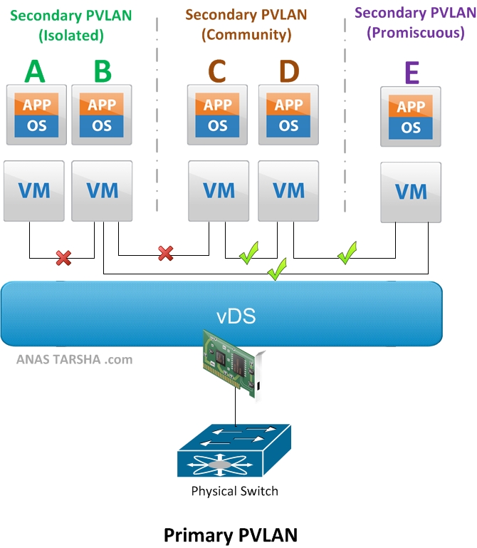
But first let me explain briefly how PVLAN works. The basic concept behind Private VLAN (PVLAN) is to divide up the existing VLAN (now referred to as Primary PVLAN) into multiple segments , called secondary PVLANs. Each Secondary PVLAN type then can be one of the following:

  • Promiscuous: VMs in this PVLAN can talk to any other VMs in the same Promiscuous PVLAN or any other secondary PVLANs. On the diagram above, VM E can communicate with A, B, C, and D.
  • Community: VMs in this secondary PVLAN can communicate with any VM in the same Community PVLAN and it can communicate with the Promiscuous PVLAN as explained above. However VMs in this PVLAN cannot talk to the Isolated PVLAN. So on the diagram, VM C and D can communicate with each other and communicate also with E.
  • Isolated: A VM in this secondary PVLAN cannot communicate with any VM in the same Isolated PVLAN nor with any VM in the Community PVLAN. It can only communicate with the Promiscuous PVLAN. So looking at the diagram again, VM A and B cannot communicate with each other nor with C or D but can communicate with E.

There are few things you need to be aware of when deploying PVLAN in a VMware vSphere environment,:

  • PVLAN is supported only on distributed virtual switches with Enterprise Plus license. PVLAN is not supported on a standard vSwitch.
  • PVLAN is supported on vDS in vSphere 4.0 or later; or on Cisco Nexus 1000v version 1.2 or later.
  • All traffic between VMs in the same PVLAN on different ESXi hosts need to traverse the upstream physical switch. So the upstream physical switch must be PVLAN-aware and configured accordingly. Note that this required only if you are deploying PVLAN on s vSphere vDS since VMware applies PVLAN enforcement at the destination while Cisco Nexus 1000v applies enforcement at the source and therefore allowing PVLAN support without upstream switch awareness.
Next I’m going to demonstrate how to configure PVLAN on VMware vDS and Cisco Nexus 1000v. Stay tuned for that. In the meantime feel free to leave some comments below.


Share This:
Facebooktwitterredditpinterestlinkedintumblrmail

Cisco Nexus 7000 FAQ

Cisco Nexus FAQ

Nexus 7000

Q. Is the FAB1 module supported with SUP2 or SUP2E?

A. Yes, supported with both supervisors.

Q. What minimum software release do I need to support SUP2 or SUP2E?

A. NX-OS 6.1

Q. Can I still run NX-OS version 6.0 on SUP1?

A. Yes.

Q. Can I upgrade SUP2 to SUP2E?

A. Yes. You would need to upgrade both the CPU and memory on board.

[8/14/2014] update: after further investigation I found that the answer is no (upgrade is not possible). 

Q. I need to enable high-availability (HA), can use one SUP1 with one SUP2 in the same chassis?

A. No, for high-availability the two supervisors must be of the same type so you would need to use either SUP1/SUP1 or SUP2/SUP2.

Q. How many I/O modules can I have in a 7004?

A. Maximum of 2. The other 2 slots are reserved for the supervisors and you cannot use them for I/O modules.

Q. FAB1 or FAB2 on 7004?

A. The Nexus 7004 chassis does not actually use any FAB’s. The I/O modules are connected back to back.

Q. How many FEX’s can the Nexus 7000 support?

A. 32 FEX’s with SUP1 or SUP2; and 48 FEX’s with SUP2E.
[8/14/2014] update: 64 FEXs with SUP2E or SUP2 

Q. How many VDC’s can the Nexus 7000 support?

A. 4 VDC’s (including 1 VDC for management) with SUP1 or SUP2; and 8 + 1 (management) VDC’s with SUP2E.

Q. Which modules support FabricPath, FCoE, and FEX connectivity?

A. FabricPath is supported on all F1 and F2 modules. FCoE is supported on all F1 modules and F2 modules except on the 48 x 10GE F2 (Copper) module. FEX is supported on all F2 modules. Use this link from Cisco as a reference.

[8/14/2014] update: The F2e module supports FCoE, FEX, and FabricPath. The F3 module (12 port 40GE) supports FEX, FabricPath, FCoE, OTV, MPLS and LISP. 

Q. Which modules support LISP, MPLS, and OTV?

A. All M1 and M2 modules support MPLS and OTV. LISP is supported only on the 32 x 10GE M1 module.

Q. Does the Nexus 7004 support SUP1?

A. No, the Nexus 7004 supports only SUP2 and SUP2E.

Q. Can I place an F2 module in the same VDC with F1 or M module?

A. No, the F2 module must be placed in a separate VDC so if you plan to mix F2 with F1, and M modules in the same chassis you would need a VDC license.

[8/14/2014] update: The F2e and F3 (12 port 40GE) modules can interoperate with the M-series in the same VDC.  

Q. How can I upgrade from FAB1 to FAB2 modules during operation without any service disruption?

A. Yes, if you replace each module within a couple of minutes. Just make sure to replace all FAB1 with FAB2 modules within few hours. If you mix FAB1 with FAB2 modules in the same chassis for a long time, the FAB2 modules will operate in backward compatible mode and downgrade their speed to match the FAB1 modules peed. You can follow this link for step-by-step procedure for upgrading the FAB modules on the Nexus 7000.

Q. Can I use FAB1 modules in a 7009 chassis?

A. No, the Nexus 7009 uses only FAB2 modules.

Q. Does the Nexus 7000 support native Fibre Channel (FC) ports?

A. No, FC ports are not supported on the Nexus 7000. You would need either the Nexus 5500 or the MDS 9000 to get FC support.


Share This:
Facebooktwitterredditpinterestlinkedintumblrmail

How To Connect HP BladeSystem c7000/c3000 To Cisco Unified Fabric

When deploying blade servers it’s always recommended to use blade switches in the chassis for cabling reduction, improved performance and lower latency. However blade switches increase the complexity of the server access layer and introduce extra layer between the servers and the network. In this post I will go though few options for connecting the popular HP C-class BladeSystem to a Cisco unified fabric.

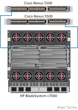
HP Virtual Connect Flex-10 Module

HP BladeSystem c7000 with Flex10 VirtualConnect

The Virtual Connect Flex-10 Module is a blade switch for the HP BladeSystem c7000 and c3000 enclosures. It reduces cabling uplinks to the fabric and offers oversubscription ratio of 2:1.

It has (16) 10GE internal connectors for downlinks and (8) 10Gb SFP+ for uplinks. This module however does not support FCoE so if you are planning on supporting Fibre Channel (FC) down the road you would need to add separate module to the chassis for storage. It also does not support QoS so that means you will need to carve up manually the bandwidth on the Flex-NICs exposed to the vSphere ESX kernel for vMotion, VM data, console, etc. This could be inefficient way of bandwidth assignment as the Flex-NIC would get only what’s assigned to it even if the 10G link is idle.

This module adds additional management point to the network as it has to be managed separately from the fabric (usually by the server team). The HP Virtual Connect Flex-10 module is around $12,000 list price.


HP 10GE Pass-Thru Module

HP BladeSystem c7000 10G Pass thru with Cisco Nexus

The HP 10GE Pass-Thru module for the BladeSystem c7000 and c3000 enclosures acts like a hub and offers 1:1 oversubscription ratio. It has 16 connectors for downlinks and (16) 1/10GE uplink ports. It supports FCoE and the uplink ports accept SFP or SFP+ optics.

As shown the picture above this module can be connected to a Nexus Fabric Extender (FEX) such as the Nexus 2232PP which offers (32) 10GE ports for server connectivity or you can connect the module to another FEX with support for only 1GE downlinks if your server do not need the extra bandwidth. This solution is more attractive than the first option of using Virtual Connect Flex-10 module because it’s pass-thru and supports FCoE so you would not need another module for storage. And because it’s a pass-through it wouldn’t act like a “man in the middle” between the fabric and the blade servers.

Finally with this solution you have the option of using VM-FEX technology on the Nexus 5500 since both the HP pass-thru module and the Nexus 2200 FEX are transparent to the Nexus 5500. This module is around $5000 list price.


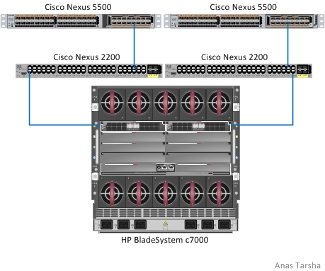
Cisco Fabric Extender (FEX) For HP BladeSystem

HP BladeSystem c7000 with Cisco Nexus B22 FEX

The Cisco B22 FEX was designed specifically to support the HP BladeSystem c7000 and c3000 enclosures. Similar to the Cisco Nexus 2200 it works like a remote card and is managed from the parent Nexus 5500 eliminating multiple provisioning and testing points. This FEX has 16 internal connectors for downlinks and (8) 10GE uplink ports. It does support FCoE and the supported features on it  are on par with the Nexus 2200.

By far this is the most attractive solution for connecting HP BladeSystem to a Cisco fabric. With this solution you need to manage only the Nexus 5500 switches and you have support for FCoE, VM-FEX, and other NX-OS features. This B22 FEX is sold by HP (not Cisco) and its priced around $10,000 list price. The Nexus 5500 supports up to 24 fabric extenders in Layer 2 mode and up to 16 fabric extenders in Layer 3 mode.


Share This:
Facebooktwitterredditpinterestlinkedintumblrmail

Cisco Nexus 2000/7000 vPC Design Options

When building data center networks using Cisco Nexus switches you can choose to attach the Nexus 2000 Fabric Extender (FEX) to a Nexus 5000 or 7000 depending on your design requirements and budget. In a previous post I briefly described the benefits of Virtual PortChannel (vPC) and discussed design options for the Nexus 2000/5500/5000. In this post I will go over the vPC design options for the Nexus 2000/7000 and important things to consider while creating the design.

Without vPC

Cisco Nexus 2000/7000 Without vPC

The picture above shows how you can connect a Nexus 2000 to its parent switch Nexus 7000 without using vPC. Topology A on the left shows a  single attached Nexus 2000 to a  7000 and a server connected to a server port on the Nexus 2000. There is no redundancy in this topology and failure of the Nexus 7000 or 2000 would cause the server to lose connectivity to the fabric. In this design you can have up to 32 FEX’s per Nexus 7000 with Sup1/2 or 48 FEX’s with Sup2E.

Topology B on the right has also no vPC and NIC teaming in this case is used for failover. The solid blue link is the primary connection and the dotted link is the backup. It’s up to the OS on the server to detect any failure upstream and fail over to the backup link. Similar to A in this design you can have up to 32 FEX’s per Nexus 7000 with Sup1/2 or 48 FEX’s with Sup2E.


With vPC


Cisco Nexus 2000/7000 vPC Design

The picture above hows the supported vPC topology for the Nexus 7000. Topology C is called straight-through vPC in which each Nexus 2000 (FEX) is connected to one parent Nexus 7000 while the server is dual attached to a pair of Nexus 2000. In this case NIC on server must support LACP so that the two FEX’s appear as a single switch. Most modern Intel and HP NIC’s support LACP today. This topology supports up to 64 FEX’s (32 per Nexus 7000) with Sup1/2 or 96 FEX’s (48 per Nexus 7000) with Sup 2E.

Maximum Supported Nexus FEX As of Today:

Nexus 7000
Without vPC32 with Sup1/2; 48 with Sup2E
Straight-through64 with Sup1/2 (32 per Nexus 7000); 96 with Sup2E (48 per Nexus 7000)

Notes:

  • The  Nexus 7000 modules that support FEX are: N7K-M132XP-12L (32 x 10GbE SFP+), N7K-F248XP-25 (48 x 10GbE SFP/SPF+), and all M2 modules. The F1, F2 copper, and 1GbE M1 modules don’t support FEX
  • All FEX uplinks must be placed in the same VDC on the Nexus 7000
  • Dual attaching the FEX to pair of Nexus 7000 is not supported as of today on the Nexus 7000 which means in the event of I/O module failure all FEX’s hanging off of that module will be knocked out. For this reason it’s recommended to have at least two IO modules in the chassis that support FEX and distribute the uplinks across those two modules for redundancy
  • If the FEX is going to be within 100 meters from the Nexus 7000, you can use Cisco Fabric Extended Transceiver (FET) on the uplinks which offers cost-effective way to connect the FEX to its parent switch. The FET is much cheaper than the 10G SFP+ optic


Share This:
Facebooktwitterredditpinterestlinkedintumblrmail

Ultra-low-latency ToR Switches For Building Scalable Leaf-Spine Fabrics

When building scalable Leaf-Spine fabrics, network architects look for low-latency, high-density switches to use at the leaf layer. There are many fixed switches that can be used for Top-0f-rack (ToR) at the leaf layer to provide connectivity upstream to the spine layer. What I’m about to compare are 3 ultra-low-latency ToR switches based on merchant silicon available in the market today for that purpose.

Cisco Nexus 3064 

The 3064 is 1 RU heigh and has a low latency and low power consumption per port. It has (48) 1/10GbE ports and (4) 40 GbE uplinks which can be each used in native 40 GbE or split into four 10GbE ports. It runs the same Nx-OS as the Nexus 7000 and 5000 series.

The Nexus 3064 is Cisco’s first switch in the Nexus family to use merchant silicon (Broadcom Trident+ chip). I’m curious to see whether Cisco will continue to use merchant silicon in future products or stick to their propreitery Nuova ASIC of the 7000 and 5000 series.


Arista 7050S-64

Arista 7050S-64 is very similar to the Cisco Nexus 3064 in terms of latency, interface types, and switching capacity. Its power consumption is less than the Nexus 3064 though. Arista’s fixed switches are known for their low power consumption and the 7050S-64 is no exception. Its power consumption is under 2W per port. You really cannot beat that!


Dell Force10 S4810

The Dell Force10 S4810 is another great ToR switch that can be used to build leaf-spine fabrics. It offers the same interface types as the Nexus 3064 and Arista 7050s-64; and similar form factor. It does however have slightly higher power consumption per port.


Ultra-low-latency 10/40 GbE Top-of-Rack Switches

Cisco Nexus 3064Arista 7050S-64Dell Force10 S4810
Ports48 x 1/10GbE SPF+ and 4 x 40GbE QSFP+48 x 1/10GbE SPF+ and 4 x 40GbE QSFP+48 x 1/10GbE SPF+ and 4 x 40GbE QSFP+
Packet Latency (64 bytes)824ns800ns700ns
OSNx-OSArista EOSFTOS
Form Factor1 RU1 RU1 RU
Switching Capacity1.28 Tbps1.28 Tbps1.28 Tbps
Power Supply2 Redundant & Hot swappable power supplies2 Redundant & Hot swappable power supplies2 Redundant & Hot swappable power supplies
Typical Operating Power177W103W220W
Full Data SheetData SheetData SheetData Sheet


Share This:
Facebooktwitterredditpinterestlinkedintumblrmail

Cisco UCS Supported IOM Connectivity Options

When connecting the UCS chassis to the Fabric interconnect, it’s important to follow the design rules or otherwise you may end up with unexpected behavior. UCS supports up to two fabric extenders (2100/2200 series) per chassis and two fabric interconnects (6100/6200 series) per cluster. To have a fully redundant system you will need two fabric extenders and two fabric interconnects connected as shown below the first picture (topology in the top right and top left).

Here are some UCS design rules to keep in mind:

  • Direct one-to-one relationship between the FEX and fabric interconnect. Meaning each Fabric Extender (FEX) can be connected only to a single fabric interconnect. You cannot dual-home a FEX. Similarly a fabric interconnect cannot connect to more than one FEX.
  • If you choose to have only one FEX in the chassis you must place that FEX into the left bay (as viewed from the rear of the enclosure)
  • When using two fabric interconnects for redundancy you must establish a cluster link between them by connecting the L1/L2 ports on the first fabric interconnect to the L1/L2 pots on the second one.

Correct IOM connectivity options:

The picture below shows the supported IOM connectivity options for UCS

Cisco UCS Supported Connectivity Options


Incorrect IOM connectivity options:

The picture below shows some unsupported IOM connectivity options for UCS

Cisco UCS unSupported Connectivity Options

The first topology (upper left) is not supported because the links between the fabric interconnects are missing

The second topology (lower left) is not supported because both FEX’s are uplinked to the same fabric interconnect.

The third topology (upper right) is not supported because the FEX is dual-homed to the fabric interconnects.

The fourth topology (lower right) is not supported because there is only one FEX in the chassis so that FEX should be placed into the left bay.


Share This:
Facebooktwitterredditpinterestlinkedintumblrmail

Cisco Nexus 2000/5000 vPC Design Options

Virtual PortChannel (vPC) allows two links that are connected to two different physical Cisco Nexus 5000 or 7000 switches to appear to the downstream device as a single PortChannel link.  That downstream device could be a server, Nexus 2000, or any Classical Ethernet switch.

vPC is useful to prevent spanning tree from blocking redundant links in the topology. After all you  have spent fortune and bought those expensive 10G ports and the last thing you want is for spanning tree to block them.

Having said that they are several ways to connect the Cisco Nexus Fabric Extender (FEX) to its parent the Nexus 5000 or 7000 switch. In this post I’m going to discuss supported vPC topologies for the Nexus series. I’m going to start with the Nexus 2000/5000 now and will add a separate post for the Nexus 2000/7000 options later.


Without vPC

Cisco Nexus 2000/5000 Without VPC

The picture above shows the supported non-vPC topologies. Topology A on the left shows a straight forward connectivity between Nexus 2000 and 5000 with a server connected to a server port on the Nexus 2000. There is no redundancy in this topology and failure of the Nexus 5000 or 2000 would cause the server to lose connectivity to the fabric. In this design you can have up to 24 FEX’s per Nexus 5500 in L2 mode and 16 FEX’s in L3.

Topology B on the right has also no vPC and NIC teaming in this case is used for failover. The solid blue link is the primary connection and the dotted link is the backup. It’s up to the OS on the server to detect any failure upstream and fail over to the backup link. Similar to A in this design you can have up to 24 FEX’s per Nexus 5500 in L2 mode and 16 FEX’s in L3.


With vPC

Cisco Nexus 2000/5000 VPC

The picture above hows the supported vPC topologies for the Nexus 5000. Topology C is called straight-through vPC in which each Nexus 2000 (FEX) is connected to one parent Nexus 5000 while server is dual-homed. In this case NIC on server must support LACP so that the two FEX’s appear as a single switch. Most modern Intel and HP NIC’s support LACP today. This topology supports up to 48 FEX’s (24 per Nexus 5500) in L2 mode and 32 FEX’s (16 per Nexus 5500) in L3 mode.

In topology D on the other hand each FEX is dual-homed and so is the server. So the NIC on the server must support LACP as in C. In this topology you can have up to 24 FEX’s in L2 mode and 16 FEX’s in L3.

Topology E is similar to D where each FEX is dual-homed but the server is single-homed. In this topology you can have up to 24 FEX’s in L2 mode and 16 FEX’s in L3.


Maximum Supported Cisco FEX As of Today:

Nexus 5000Nexus 5500
Without vPC (L2 Mode)1224
Without vPC (L3 Mode)X16
Straight-through (L2 Mode)24 (12 per Nexus 5000)48 (24 per Nexus 5500)
Straight-through (L3 Mode)X32 (16 per Nexus 5500)
Dual-homed FEX (L2 Mode)1224
Dual-homed FEX (L3 Mode)x16

Share This:
Facebooktwitterredditpinterestlinkedintumblrmail