Page 2 of 4

Troubleshooting vMotion Connectivity Issues

I attended a panel discussion session at VMUG this week. A guy from the audience asked a question on how to troubleshoot connectivity issues after moving a VM. The guy had a one flat VLAN with one IP subnet and every time he vMotioned a VM to another host, users lost connectivity with that VM.

To answer his question, a guy on the stage advised him to recreate another VLAN/IP subnet, move that VM to the newly created subnet, and then try to do the vMotion again.

Well obviously that wasn’t a good advice and changing the VM IP address in this case would not help. In this post I will explain what happens when a VM moves and steps you can take to troubleshoot network delay and connectivity issues related to vMotion.

First before you do any vMotion, ensure that the VLAN is configured on all switches and allowed on all necessary trunk ports in the network. You can use the commands show vlan and show trunk to verify that that.

When you create a new VM, the host allocates and assigns a MAC address to that VM. The physical switch which the host is connected to eventually learns the VM MAC address (that happens when the VM ARPs for its gateway, starts sending traffic and the switch sees that traffic, or when the Notify Switches in vSphere option is tuned on).

When a VM moves to another host (the new host could be either connected to another port or the same physical switch or connected to a different switch), somebody has to tell the network to change its destination port for that MAC address in order to continue to deliver traffic to that VM. In vSphere that is usually handled by the host when the “Notify Switches” option is turned on. The host in this case notifies the network by sending several RARP messages on behalf of the VM to ensure that the upstream physical network updates its MAC table.

So the first step in troubleshoot this specific issue is to ensure that the “Notify Switches” settings is set to Yes before you vMotion the VM. In vSphere 5.5 you would go to the vSwitch/vDS settings and then to Teaming and Failover to verify the setting.  

Notify switches


If that does not help, try to do the followings:

On the physical switch (the switch the destination host is connected to), issue a command to look up MAC table and find out which destination port the switch is using to reach the VM. On a Cisco Catalyst switch, you can use the “show mac address-table” command for example. If the switch is still using the old MAC-to-port mapping, then it’s either that the switch is not reaching the RARP notification from the host or the host itself is not sending it.

If you don’t do anything to correct the problem, the aging timer for that MAC address on the switch (default is set to 5 mins on Cisco switches) will eventually expire and the switch will learn the MAC address via the new port but to speed things up you can alway flush out the VM MAC address from the switch MAC table (clear mac address-table on Cisco catalyst).

Obviously having to manually intervene and troubleshoot every time you move a VM defeats the whole purpose of vMotion. vMotion is supposed to do live migration of a VM and preserves all active network connections during the process. But hopefully the above steps will give you some pointers on where to look and start to find the root cause.

Additionally VMware recommends disabling the followings on the physical ports connected to the host to minimize networking delay:

– Port Aggregation Protocol (PAgP) and Link Aggregation Control Protocol (LACP). 

– Dynamic Trunking Protocol (DTP) or trunk negotiation.

– Spanning Tree Protocol (STP).


Share This:
Facebooktwitterredditpinterestlinkedintumblrmail

Building A Private Cloud – Introduction


I’m starting a new post series to walk you through building a private cloud. This post is the first one in the series and will be just an introduction to private clouds. 


In the next posts I will discuss collecting the requirements, building the network and network services, building the storage, designing the server infrastructure, and putting the orchestration layer on top of that.   


Why Private Cloud?


There are number of public cloud providers out there that have good and affordable offerings. However customers sometimes prefer private cloud over public cloud for specific reasons or requirements they need to meet. Here are some the reasons that come to mind:


  • Regulatory Compliance: Some companies have have to comply with certain regulations and therefore have to keep their customer data or their own data on dedicated/isolated infrastructure behind their firewall. In this case the multi-tenant public cloud model won’t be a good fit for them.
  • Control: Some companies require more control over the cloud infrastructure than what public cloud providers usually offer or they might have a specific need to integrate a solution/product from certain vendor. Most public cloud providers offer standard services that may not be customized or tweaked easily. 
  • Avoid Lock-in: I’m sure you heard this before. People don’t like to put all of their eggs in one basket nor like to heavily rely on a specific vendor/provider. By building their own cloud in house companies can have the freedom of choosing multiple vendors and can also leverage open source technology if they wish.
  • Cost: This might be a bit of surprise to you but depending on how much the monthly bill coming from the public cloud provider is, operating a private cloud might become a cheaper option. This is especially true if you are using the cloud to run production workloads that need to be up 24/7 and cannot be turned off while not in use.  


Barriers to Private Cloud Deployments:


  • Lack of Technical Resources: Designing, implementing, and supporting a private cloud require having the right IT resources in house. Some companies just don’t have that.
  • Time to Market: Getting a private cloud up and running is at least 6-12 month long process. Some companies have to respond to market pressure quickly and simply don’t have the luxury of spending a year to build a cloud in house.
  • Cost: Building and operating a private cloud is expensive and it makes more sense in some cases to  leverage a public cloud offering than spending that CapEx up front.


You have the capital and technical talent and want to build a private cloud? Great. In the next post I will walk you through the process of collecting the requirements and making high-level design decisions before we get into building the infrastructure itself. Stay tuned.


Make sure that you either subscribe to my blog or follow me on Twitter to get notified when I add a new content.


Anas


Share This:
Facebooktwitterredditpinterestlinkedintumblrmail

Deploying Secure Hybrid Cloud Extension Using LISP For Workload Mobility – Part 2

This post assumes a working knowledge of Locator/ ID Separation Protocol (LISP), you may first want to review Part 1 before reading through this post.

In Part 1 we created two LISP sites and enabled connectivity between these two sites. We also enabled VM mobility and showed how you can migrate a VM to the cloud without changing its IP address, mask, or default gateway.

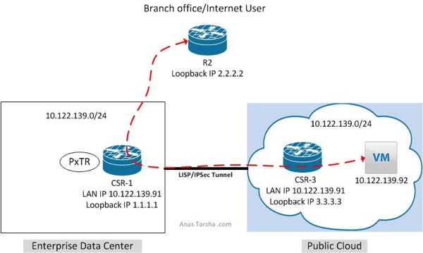
In this post I will expand on Part 1 and enable connectivity between non-LISP and LISP sites. As shown in the diagram below I have a branch office (non-LISP site) which needs to reach the VM (IP address 10.122.139.91) in the cloud.

LISP2

To do so we have three design options…

Option 1 is to enable LISP on the branch edge router. In this design traffic leaving the branch will be redirected by the branch edge router to the cloud however this option is costly and requires deploying a router with LISP support on each branch router.

Option 2 is to deploy a LISP proxy router in the service provider WAN to intercept traffic and re-direct it to cloud. This option is less expensive than option 1 but requires routing all traffic thru the proxy router which could cause this router to become a choke point.

Option 3 is to configure the already LISP-enabled router in the data center as proxy which will redirect traffic to the cloud. This is the least expensive option but obviously does not provide optimal routing as you need to backhaul traffic to the data center first, however this might be acceptable design when local internet access is not available at the branch and internet-bound traffic needs to traverse the data center anyway or when the customer wants the traffic from the branch to traverse the data center firewall first for policy enforcement.

In this post I will show you what you need to do to enable option 3.

To add the proxy functionality to the design, first we need to configure CSR1 as Proxy Tunnel Router (PxTR) which tells CSR1 to intercept the traffic coming from any non-LISP site and redirect it to the cloud:

CSR_1#sh run | i ipv4

 no ipv4 itr

 ipv4 proxy-etr

 ipv4 proxy-itr 1.1.1.1

Now if I run a show command I can see that CSR1 is configured as PxTR:

CSR_1#sh ip lisp

  Instance ID:                      0

  Router-lisp ID:                   0

  Locator table:                    default

  EID table:                        default

  Ingress Tunnel Router (ITR):      disabled

  Egress Tunnel Router (ETR):       enabled

  Proxy-ITR Router (PITR):          enabled RLOCs: 1.1.1.1

  Proxy-ETR Router (PETR):          enabled

The second step is to configure CSR3 to use CSR1 as its default proxy ETR (PETR). This is necessary as CSR3 is not going to know how to get back to the source 2.2.2.2 since this prefix is not a LISP entry and does not exist in its cache table.

CSR_3# show run | b lisp

 router lisp

 ipv4 use-petr 1.1.1.1

Now let’s run a ping test from R2 (2.2.2.2) to see if we can reach the VM:

R2#ping 10.122.139.92 source 2.2.2.2

Type escape sequence to abort.

Sending 5, 100-byte ICMP Echos to 10.122.139.92, timeout is 2 seconds:

Packet sent with a source address of 2.2.2.2 

!!!!!

Success rate is 100 percent (5/5), round-trip min/avg/max = 48/51/63 ms


Comment below if you have any questions. Also please help me spread out the word if you like this post and share with your network on Twitter/Facebook/Linkedin.


Anas

Twitter: @anastarsha


Share This:
Facebooktwitterredditpinterestlinkedintumblrmail

Let’s Connect at VMworld 2014 In San Francisco

I’m attending VMworld 2014 in San Fracisco from Aug 24-28. I like to meet new people so feel free to schedule time with me if you are:

– A fellow networking professional and want to meet up or

– A vendor and would like me to review a new solution/feature you have or

– A customer and interested in chatting about a specific design or technology

Contact me by filling the online form and I will get back to you shortly.


See you in San Francisco!

Screen Shot 2014 05 08 at 8 28 55 PM


Share This:
Facebooktwitterredditpinterestlinkedintumblrmail

How to Enable SSH RSA Authentication On Cisco Device

If you have been around Cisco devices for a while you probably know how to enable them for SSH access and log in using a username/password. Yesterday however I ran into a situation while deploying Ansible where i needed to enable logging in to the router using an RSA key instead of a password and had to try few things to get it to work.

Why would you want to use RSA based user authentication for SSH instead of a password based authentication?

1- RSA keys are much more secure than passwords. Passwords (even when they are stronger than your dog’s name) are susceptible to brute-force attacks and can be compromised

2- Using RSA key is easier as you don’t have to enter or remember your password every time

3- You might need to use RSA authentication if you are using management or automation tools (such as Ansible) to manage the devices via SSH.

Here is what you need to do to enable SSH RSA authentication on a Cisco router:

Step 1: Enable the router for SSH server by entering the following commands:

ip domain name example.com

!

!generate the RSA key for SSH

crypto key generate rsa

!

username bob password 0 smith

!

line vty 0 98

 login local

At this point you should be able to SSH to the router using the username/password defined in the configs above. Fix any issues you may have before you move on to the next step. A good debug command to use for troubleshooting is: debug ip ssh  


Step 2: Enable Public/RSA Key Authentication

First make sure that you generate a public/private key pair on the machine you are trying to SSH from if you don’t already have one. SecureCRT and Putty for Windows have a built-in program to generate the key pair. If you are on a Mac or a Linux/Unix machine, you can use the command ssh-keygen to generate the key pair.

Next enter the following commands on the router:

R_Ent(config)#ip ssh pubkey-chain

R_Ent(conf-ssh-pubkey)#username bob

R_Ent(conf-ssh-pubkey-user)#key-string

R_Ent(conf-ssh-pubkey-data)#!ENTER YOUR PUBLIC KEY HERE

R_Ent(conf-ssh-pubkey-data)#exit

R_Ent(conf-ssh-pubkey-user)#end

 At this point you should be able to SSH to the router without entering a password:

MacBook-Pro$ ssh [email protected] -i MyPrivateKey

R_Ent#


Bonus:

If you need to allow only SSH and disable telnet and other type of access on the router, you can do so by entering:

line vty 0 98

 transport input ssh


Anas

Twitter: @anastarsha


Share This:
Facebooktwitterredditpinterestlinkedintumblrmail

Deploying Secure Hybrid Cloud Extension Using LISP For Workload Mobility – Part 1

There are times when you want to leverage public cloud but want to keep some workloads in your data center. You can do that with Hybrid Cloud.

According to Gartner the most important use case for Hybrid Cloud is cloud bursting. That’s running the workloads internally in the data center and bursting to a public cloud during peak times. The other common use cases for hybrid cloud is disaster recovery where you migrate the workloads to a public cloud during disasters or maintenance windows.

Migrating a workload to the cloud is time consuming especially if you have to re-IP all the VMs.

In this post I will show how to migrate an application to the cloud without changing its IP address, mask, default gateway, or security policies. This makes the migration easier especially if you are migrating the workload temporarily and do not want to change the IP addresses or DNS settings.

Why I Like This Solution

You can certainly enable workload mobility between two data centers using a Layer 2 extension technology such as VPLS or Cisco OTV. However I prefer LISP over any L2 extension simply because it’s based on Layer 3 and therefore does not exntend the broadcast/failure domain like L2 extensions and you get all the benefits and scale of L3 routing.

I also think that using LISP is better than relying on any cloud extension technology like Cisco Nexus 1000v InterCloud or Verizon CloudSwitch because those technologies add a shim layer to allow the VM to run in a cloud provider environment and that degrades the VM performance. With this LISP design the VM runs natively on the hypervisor and behaves like any VM local to the cloud provider environment.

Prerequisites

– To get this solution to work to you need two Cisco routers that support Locator/ID Separation Protocol (LISP). The data center router can be either virtual or physical while the cloud provider router has to be virtual. I will be using here two Cisco CSR 1000v routers running IOS XE 3.12S for this solution.

– I will briefly explain how LISP works along the way and will be focusing only on the required components for this design. You can find more information on LISP on Cisco.com

– I will be using Verizon Terremark as my cloud provider. You may use other providers like Microsoft Azure or AWS if you wish.

Before The Migration LISP before

The diagram above shows a VM running in a data center/private cloud with IP address 10.122.139.92. The default gateway for this VM is currently CSR-1 and from the outside DNS resolves to the VM public IP address which is part of the data center addressing scheme. Now because CSR-1 is a LISP enabled router and because it’s also acting as a LISP map-server/map-resolver, it will cache the VM IP address in its database so it can inform other LISP routers about the VM location when asked.

In the cloud provider, CSR-3 is also a LISP enabled router and configured to query CSR-1 for any hosts trying to reach. So if CSR-3 receives any traffic destined for the VM it queries CSR-1 for the location of that VM. CSR-1 replies back to CSR-3 and tells it to encapsulate and send all traffic designed for the VM to him because the VM is located on its LAN.

The output below shows that the VM is located on CSR-1 local subnet at the moment:

CSR_1#sh ip lisp forwarding eid local

Prefix

10.122.139.92/32

The next output below shows that CSR-1 (1.1.1.1) is currently the locator for the VM:

CSR_1#sh ip lisp data

LISP ETR IPv4 Mapping Database for EID-table default (IID 0), LSBs: 0x1, 2 entries


10.122.139.92/32, dynamic-eid Cloud-dyn, locator-set DC1

  Locator  Pri/Wgt  Source     State

  1.1.1.1    1/100  cfg-addr   site-self, reachable

 On CSR-3 if I issue “where is the VM” command I see that CSR-1 (1.1.1.1) is currently the locator:

CSR_3#lig 10.122.139.92

Mapping information for EID 10.122.139.92 from 10.0.20.1 with RTT 49 msecs

10.122.139.92/32, uptime: 00:02:28, expires: 23:59:59, via map-reply, complete

  Locator  Uptime    State      Pri/Wgt

  1.1.1.1  00:02:28  up           1/100

That’s good. Both routers are in sync and know that the VM is located in the data center. Let’s now migrate this bad boy to the public cloud.

  After the Migration LISP after

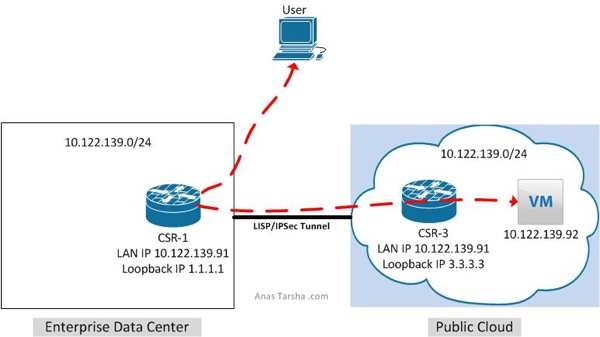
Now the VM has migrated (cold migration) to public cloud as shown in the diagram above. When the VM boots up of the first time it will ARP for its default gateway (which is CSR-3 in this case). When CSR-3 detects that the VM is now on its LAN it registers it with the map-server (CSR-1) and declares itself as the new locator for that VM. Now the DNS mapping for the VM has not changed and the outside world still thinks that the VM resides in the enterprise data center.  So when CSR-1 receives traffic destined for that VM it does a lookup in its database, encapsulates the traffic, and sends it to the new locator (CSR-3) which in turn decapsualtes the traffic and sends it off to the VM.

Now back to the router CLI. If I issue the “where is the VM now” command again, I see that CSR-3 (3.3.3.3) is now the locator:

CSR_1#lig 10.122.139.92

Mapping information for EID 10.122.139.92 from 10.0.20.3 with RTT 48 msecs

10.122.139.92/32, uptime: 00:02:27, expires: 23:59:59, via map-reply, complete

  Locator  Uptime    State      Pri/Wgt

  3.3.3.3  00:02:27  up           1/100

 If I ping the VM from CSR-1 sourcing my packets from the LAN interface, the ping is successful:

CSR_1#ping 10.122.139.92 source loopback 10

Type escape sequence to abort.

Sending 5, 100-byte ICMP Echos to 10.122.139.92, timeout is 2 seconds:

Packet sent with a source address of 10.10.10.1

.!!!!

Success rate is 80 percent (4/5), round-trip min/avg/max = 47/47/48 ms


Conclusion

LISP allows migrating workloads to the cloud without relying on L2 extensions. Use this design if you are migrating your workload temporarily. If you are migrating the workload permanently you might want to consider adding a LISP router at the WAN edge or at the branch office to redirect user traffic to the public cloud provider before its enters the enterprise data center.

Ping me if you want the full configurations.

Part 2 of this post is coming soon, make sure to subscribe to the blog or follow me on Twitter to get notified when new content is added.


Anas

Twitter: @anastarsha


Share This:
Facebooktwitterredditpinterestlinkedintumblrmail

New Course Starting Soon- Learn Cloud Computing At Your Own Pace

I’m in the process of putting together a new course called Introduction to Cloud Computing. It will be delivered via  email so you can work at your own pace and above all it’s free. If you are interested go ahead and subscribe below to receive the weekly emails from me once the course starts. The course starts in October and runs for 6 weeks. You may unsubscribe at any time.

Here is what you will learn in this course:

Week 1 – The Basics of Cloud Computing

Week 2 – Is Cloud Right For Your Business?

Week 3 – Cloud Models: Private, Public, and Hybrid Cloud

Week 4 – Cloud Storage

Week 5 – Overview of Cloud Architecture

Week 6 – Migrating to The Cloud


Share This:
Facebooktwitterredditpinterestlinkedintumblrmail

Building A New Home Lab – Phase 1

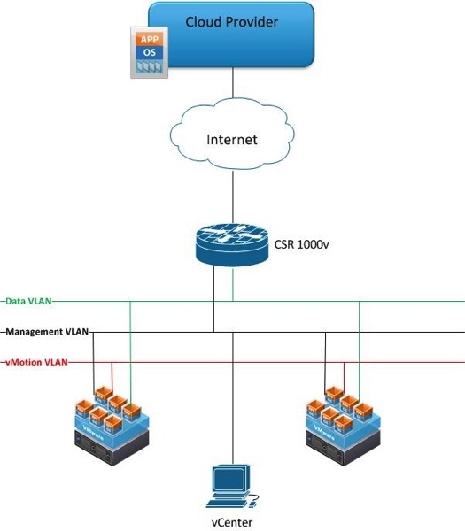
I have big goals set for this year and one of the things I need to archive these goals is a home lab to train on OpenStack, network virtualization, hypervisor networking, and just virtualization in general. In this post I will be sharing some details on my new home lab which I’m in the process of building.

For me the one thing I was trying to avoid was investing in physical hardware as I don’t have much space at the moment to place the servers. So far I have managed to run everything in Virtual Machine (VM) form factor. However as the lab grows I will probably need to invest in some physical servers.


Few Upgrades First

Before deploying any VMs I had to do some upgrades:

 – Upgraded from VMware Fusion 4.0 to 6.0 Professional on my iMac which is 30% faster than 4.0 and supports creating additional virtual networks (similar to Network Editor in VMware Workstation)

– Upgraded my iMac memory from 12GB to 16GB to make room for additional VMs


Spinning Up VMs

I then deployed the following VMs:

A Cisco CSR 1000v router as an internet gateway where I do packet filtering and run IPSec VPN with my cloud provider.

– 2 x VMware ESXi 5.5 hosts running on Fusion for VM mobility, HA, etc..

 – VMware vCener 5.5 server running on Windows 2008 server to mange the two ESXi hosts (I will be also trying the vCenter virtual appliance shortly)

– Windows 7 VM to run the vSphere Client and run other monitoring/debugging tools. 

I will be sharing over the next few weeks some interesting use cases I have been working on. Make sure to subscribe to the blog to get notified when I add new content.

Let the fun begin!

Homelab


Share This:
Facebooktwitterredditpinterestlinkedintumblrmail

Spin up Cisco CSR 1000v in VMware Fusion in 5 Minutes

I have been using the Cisco CSR 1000v as a default gateway in my home lab and I run an IPSec tunnel & LISP between it and my cloud provider (more on LISP in a separate post). The CSR 1000v runs on VMware ESXi, Microsoft Hyper-V, and Amazon Xen hypervisors but it can also run on a laptop/desktop hypervisor like VirtualBox or VMWare Fusion for testing or training purposes.

In this post I will show how to spin up a CSR 1000v instance in VMware Fusion for Mac.


Requirements:

1) I’m running VMWare Fusion 6.0 Professional but you can also run this virtual router on Fusion 4 or 5. I highly recommend using Fusion 5 Professional or 6 Professional if you want to create additional networks and assign the CSR 1000v interfaces to those networks. The feature to add additional networks (similar to Network Editor in VMWare Workstation) was added by VMWare in Fusion 5 Professional and it’s not available in the standard edition of Fusion. Alternatively if you don’t want to pay the extra bucks for the Professional edition, you can use this free tool from Nick Weaver to create the networks if you are running the standard edition. Nick’s tool isn’t the best but it does the job.

2) Go to Cisco and download the latest and greatest software version of the CSR 1000v. The CSR runs Cisco IOS XE and you need to download the OVA package for the deployment.

 
Installation:

The installation process is simple and quick:

1- Launch Fusion and go to File -> New from the top bar menu

2- Once the Installation wizard starts click on More options.  Select Install an existing virtual machine and click Continue.

3- On the next screen click Choose File. Navigate to the folder containing the OVA package, select the file, and click Open and then Continue.

4-  The next window will ask you to save the VM name, choose a name and click Save.

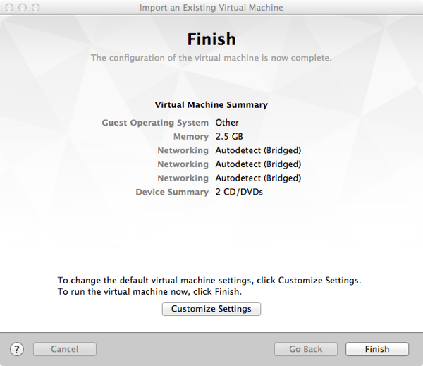
5- The final step of the wizard is to either customize or click fire up the VM. The CSR 1000v by default comes with three interfaces. If you need to add more interfaces click on Customize, otherwise click Finish.

Finish

 
6- Once you click Finish, the CSR 1000v will boot a couple of times and then you will be in traditional Cisco router User Mode.

 
Interfaces Management:

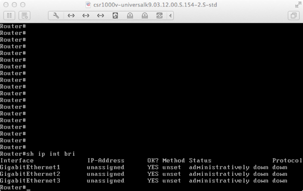
Enter Exec mode and enter “show ip int bri” to see the three interfaces. 

CSR interfaces


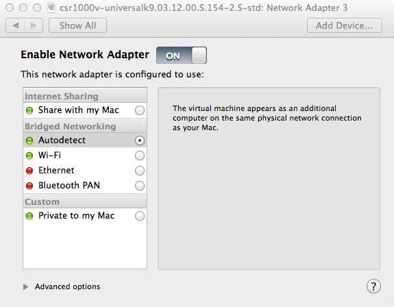
By default interfaces will become part of the Ethernet or WiFi network (that’s done by Fusion) depending on which adapter is active during the installation and you can assign from here IP interfaces and default gateway.

Adapter setting


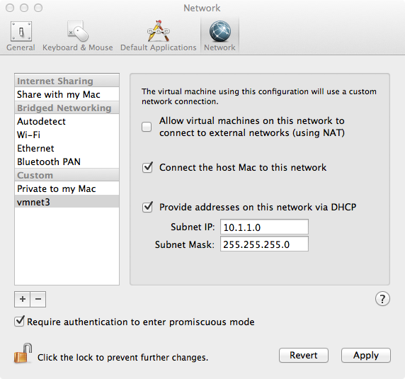
If you wish to put the interfaces on separate networks (VLANs), select the CSR VM and go to Virtual Machine -> Setting and choose the desired Network Adapter. You may also create custom networks by going to VMWare Fusion -> Preferences -> Network. From there add the + sign to add additional network and choose wether to enable DHCP or not.  

Add network


Activating The License

In order to enable the full features of the CSR 1000v, you need to purchase a license from Cisco. If you want to try the full features before purchasing, Cisco offers 60 day free trial license. To activate the free trial license, go into the router configuration mode and enter: license boot level premium. You will be asked to boot the router after you enter the command.   


Share This:
Facebooktwitterredditpinterestlinkedintumblrmail

Using Cisco CSR 1000v As Secure VPN Gateway To Extend Network To The Cloud

Cisco Services Cloud Router (CSR) 1000v is a virtual router you can deploy either in private/public cloud or in a virtualized data center.

One of the common use cases for the CSR 1000v is a secure VPN gateway in the cloud to terminate VPN tunnels. So if you run some applications in the cloud and you want to allow your branch offices to access those application over a secure network, you can run IPsec tunnels between those branch offices and the CSR 1000v in the cloud. From performance perspective this would work much better than back hauling the traffic to the data center (HQ) and then to the cloud.

In this post I will show you how to set up a VPN tunnel between Cisco CSR 1000v and a branch office router using Cisco Easy VPN. You may also use standard IPSec VPN but in my configurations I use Easy VPN because it’s, well, easier 🙂

The following configurations are part of a demo I gave at Cisco Live 2013 in Orlando where the CSR 1000v was the VPN server and the branch server (Cisco 2900 in this case) was the VPN client.

If you would like to learn how to install the CSR 1000v on Verizon Terremark eCloud, follow these steps in my post.

You will also need to open UDP port 500 and IP protocol ID 50 (ESP) on all firewalls sitting between the CSR 1000v and the branch router for the IPSec tunnel to be established successfully. Additionally depending on your design you may need to configure NAT.

In my setup, I’m using:

  • Cisco CSR 1000v with IOS XE 3.9x running in Verizon Terremark Enterprise Cloud
  • Cisco 2900 running IOS 153.2.T (branch office)

Here are the configs of the CSR 1000v (VPN Server). Only relevant configs are shown:

CSR-1#sh run
hostname CSR-1
!
aaa new-model
!
!
aaa authentication login hw-client-groupname local
aaa authorization network hw-client-groupname local
!
!
aaa session-id common
!
!
username myusername password 0 mypassword
!
!
crypto isakmp policy 1
encr 3des
authentication pre-share
group 2
crypto isakmp client configuration address-pool local dynpool
!
crypto isakmp client configuration group hw-client-groupname
key hw-client-password
dns 8.8.8.8
domain domain.com
pool dynpool
save-password
!
!
crypto ipsec transform-set transform-1 esp-3des esp-sha-hmac
mode tunnel
!
!
!
crypto dynamic-map dynmap 1
set transform-set transform-1
reverse-route
!
!
crypto map dynmap client authentication list hw-client-groupname
crypto map dynmap isakmp authorization list hw-client-groupname
crypto map dynmap client configuration address respond
crypto map dynmap 1 ipsec-isakmp dynamic dynmap
!
!
!
interface GigabitEthernet2
description WAN
ip address 10.22.36.71 255.255.255.224
negotiation auto
crypto map dynmap
!
interface GigabitEthernet3
description LAN
ip address 10.22.39.91 255.255.255.240
negotiation auto
!
ip local pool dynpool 192.168.1.1
!
!
ip access-list extended split_t
permit ip 10.22.39.0 0.0.0.255 any
!
end

Here are the configs for the Cisco 2900 router (VPN client).


no aaa new-model
!
ip cef
!
!
username vpntest password 0 vpntest
!
!
crypto ipsec client ezvpn hw-client
connect auto
group hw-client-groupname key hw-client-password
mode client
peer 10.22.36.71
username myusername password mypassword
xauth userid mode local
!
!
interface GigabitEthernet0/0
description WAN
ip address 10.35.120.104 255.255.255.0
duplex auto
speed auto
crypto ipsec client ezvpn hw-client
!
interface GigabitEthernet0/1
description LAN
ip address 172.16.4.102 255.255.255.0
duplex auto
speed auto
crypto ipsec client ezvpn hw-client inside
!
ip route 0.0.0.0 0.0.0.0 10.35.120.1
!
end 

Note: You can also install the CSR 1000v as a VM in VMware Fusion or Oracle VirtualBox if you want to play.


Share This:
Facebooktwitterredditpinterestlinkedintumblrmail
« Older posts Newer posts »