This post assumes a working knowledge of Locator/ ID Separation Protocol (LISP), you may first want to review Part 1 before reading through this post.
In Part 1 we created two LISP sites and enabled connectivity between these two sites. We also enabled VM mobility and showed how you can migrate a VM to the cloud without changing its IP address, mask, or default gateway.
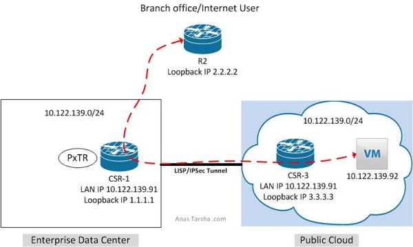
In this post I will expand on Part 1 and enable connectivity between non-LISP and LISP sites. As shown in the diagram below I have a branch office (non-LISP site) which needs to reach the VM (IP address 10.122.139.91) in the cloud.
To do so we have three design options…
Option 1 is to enable LISP on the branch edge router. In this design traffic leaving the branch will be redirected by the branch edge router to the cloud however this option is costly and requires deploying a router with LISP support on each branch router.
Option 2 is to deploy a LISP proxy router in the service provider WAN to intercept traffic and re-direct it to cloud. This option is less expensive than option 1 but requires routing all traffic thru the proxy router which could cause this router to become a choke point.
Option 3 is to configure the already LISP-enabled router in the data center as proxy which will redirect traffic to the cloud. This is the least expensive option but obviously does not provide optimal routing as you need to backhaul traffic to the data center first, however this might be acceptable design when local internet access is not available at the branch and internet-bound traffic needs to traverse the data center anyway or when the customer wants the traffic from the branch to traverse the data center firewall first for policy enforcement.
In this post I will show you what you need to do to enable option 3.
To add the proxy functionality to the design, first we need to configure CSR1 as Proxy Tunnel Router (PxTR) which tells CSR1 to intercept the traffic coming from any non-LISP site and redirect it to the cloud:
CSR_1#sh run | i ipv4
no ipv4 itr
ipv4 proxy-etr
ipv4 proxy-itr 1.1.1.1
Now if I run a show command I can see that CSR1 is configured as PxTR:
CSR_1#sh ip lisp
Instance ID: 0
Router-lisp ID: 0
Locator table: default
EID table: default
Ingress Tunnel Router (ITR): disabled
Egress Tunnel Router (ETR): enabled
Proxy-ITR Router (PITR): enabled RLOCs: 1.1.1.1
Proxy-ETR Router (PETR): enabled
The second step is to configure CSR3 to use CSR1 as its default proxy ETR (PETR). This is necessary as CSR3 is not going to know how to get back to the source 2.2.2.2 since this prefix is not a LISP entry and does not exist in its cache table.
CSR_3# show run | b lisp
router lisp
ipv4 use-petr 1.1.1.1
Now let’s run a ping test from R2 (2.2.2.2) to see if we can reach the VM:
R2#ping 10.122.139.92 source 2.2.2.2
Type escape sequence to abort.
Sending 5, 100-byte ICMP Echos to 10.122.139.92, timeout is 2 seconds:
Packet sent with a source address of 2.2.2.2
!!!!!
Success rate is 100 percent (5/5), round-trip min/avg/max = 48/51/63 ms
Comment below if you have any questions. Also please help me spread out the word if you like this post and share with your network on Twitter/Facebook/Linkedin.
Anas
Twitter: @anastarsha
Share This:

Leave a Reply