Category: Cisco Nexus

Private VLAN and How It Affects Virtual Machine Communication

Private VLAN (PVLAN) is a security feature which has been available for quite some time on most modern switches. It adds a layer of security and enables network admins to restrict communication between servers in the same network segment (VLAN). So for example let’s say you have an Email and Web servers in the DMZ in the same VLAN and you don’t want them to communicate with each other but still want each server to communicate with the outside world. Obviously one way to prevent the servers from talking directly to each other is to place each server in a separate VLAN and apply ACLs on the firewall/router preventing communication between the two VLANs. This solution though requires using multiple VLANs and IP subnets. It also requires you to re-IP the servers in an existing environment. But what if you are running out of VLANs or IP subnets and/or re-IPing is too disruptive? Well then you can use PVLAN instead.

With PVLAN you can provide network isolation between servers or VMs which are in the same VLAN without introducing any additional VLANs or having to use MAC access control on the switch itself. 

While you can configure PVLAN on any modern physical switch, this post will focus on deploying PVLAN on a virtual distributed switch in a VMware vSphere environment.  

Private VLAN and Vmware vSphere

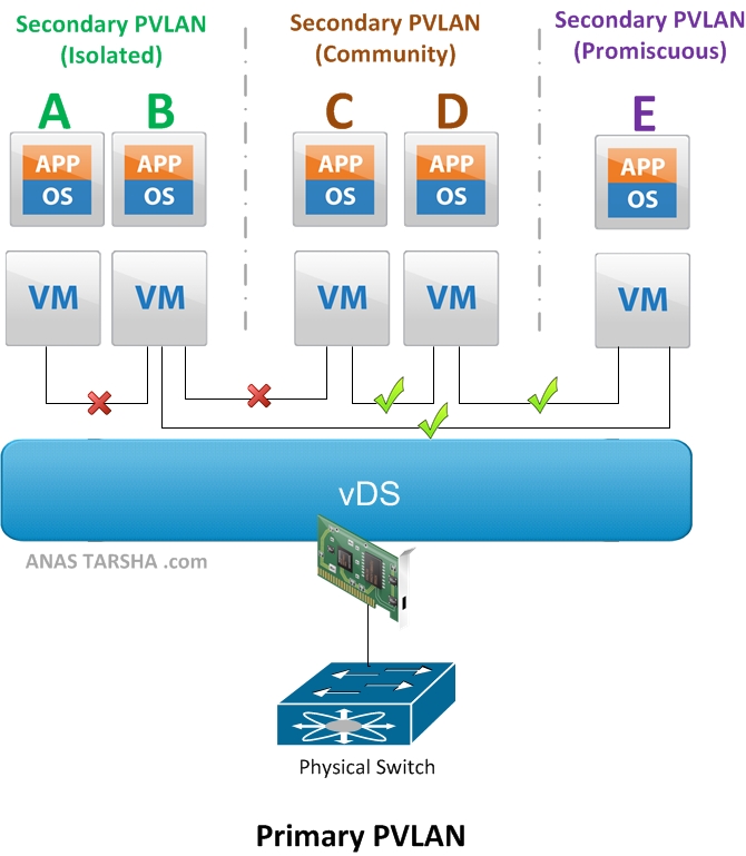
But first let me explain briefly how PVLAN works. The basic concept behind Private VLAN (PVLAN) is to divide up the existing VLAN (now referred to as Primary PVLAN) into multiple segments , called secondary PVLANs. Each Secondary PVLAN type then can be one of the following:

  • Promiscuous: VMs in this PVLAN can talk to any other VMs in the same Promiscuous PVLAN or any other secondary PVLANs. On the diagram above, VM E can communicate with A, B, C, and D.
  • Community: VMs in this secondary PVLAN can communicate with any VM in the same Community PVLAN and it can communicate with the Promiscuous PVLAN as explained above. However VMs in this PVLAN cannot talk to the Isolated PVLAN. So on the diagram, VM C and D can communicate with each other and communicate also with E.
  • Isolated: A VM in this secondary PVLAN cannot communicate with any VM in the same Isolated PVLAN nor with any VM in the Community PVLAN. It can only communicate with the Promiscuous PVLAN. So looking at the diagram again, VM A and B cannot communicate with each other nor with C or D but can communicate with E.

There are few things you need to be aware of when deploying PVLAN in a VMware vSphere environment,:

  • PVLAN is supported only on distributed virtual switches with Enterprise Plus license. PVLAN is not supported on a standard vSwitch.
  • PVLAN is supported on vDS in vSphere 4.0 or later; or on Cisco Nexus 1000v version 1.2 or later.
  • All traffic between VMs in the same PVLAN on different ESXi hosts need to traverse the upstream physical switch. So the upstream physical switch must be PVLAN-aware and configured accordingly. Note that this required only if you are deploying PVLAN on s vSphere vDS since VMware applies PVLAN enforcement at the destination while Cisco Nexus 1000v applies enforcement at the source and therefore allowing PVLAN support without upstream switch awareness.
Next I’m going to demonstrate how to configure PVLAN on VMware vDS and Cisco Nexus 1000v. Stay tuned for that. In the meantime feel free to leave some comments below.


Share This:
Facebooktwitterredditpinterestlinkedintumblrmail

Cisco Nexus 7000 FAQ

Cisco Nexus FAQ

Nexus 7000

Q. Is the FAB1 module supported with SUP2 or SUP2E?

A. Yes, supported with both supervisors.

Q. What minimum software release do I need to support SUP2 or SUP2E?

A. NX-OS 6.1

Q. Can I still run NX-OS version 6.0 on SUP1?

A. Yes.

Q. Can I upgrade SUP2 to SUP2E?

A. Yes. You would need to upgrade both the CPU and memory on board.

[8/14/2014] update: after further investigation I found that the answer is no (upgrade is not possible). 

Q. I need to enable high-availability (HA), can use one SUP1 with one SUP2 in the same chassis?

A. No, for high-availability the two supervisors must be of the same type so you would need to use either SUP1/SUP1 or SUP2/SUP2.

Q. How many I/O modules can I have in a 7004?

A. Maximum of 2. The other 2 slots are reserved for the supervisors and you cannot use them for I/O modules.

Q. FAB1 or FAB2 on 7004?

A. The Nexus 7004 chassis does not actually use any FAB’s. The I/O modules are connected back to back.

Q. How many FEX’s can the Nexus 7000 support?

A. 32 FEX’s with SUP1 or SUP2; and 48 FEX’s with SUP2E.
[8/14/2014] update: 64 FEXs with SUP2E or SUP2 

Q. How many VDC’s can the Nexus 7000 support?

A. 4 VDC’s (including 1 VDC for management) with SUP1 or SUP2; and 8 + 1 (management) VDC’s with SUP2E.

Q. Which modules support FabricPath, FCoE, and FEX connectivity?

A. FabricPath is supported on all F1 and F2 modules. FCoE is supported on all F1 modules and F2 modules except on the 48 x 10GE F2 (Copper) module. FEX is supported on all F2 modules. Use this link from Cisco as a reference.

[8/14/2014] update: The F2e module supports FCoE, FEX, and FabricPath. The F3 module (12 port 40GE) supports FEX, FabricPath, FCoE, OTV, MPLS and LISP. 

Q. Which modules support LISP, MPLS, and OTV?

A. All M1 and M2 modules support MPLS and OTV. LISP is supported only on the 32 x 10GE M1 module.

Q. Does the Nexus 7004 support SUP1?

A. No, the Nexus 7004 supports only SUP2 and SUP2E.

Q. Can I place an F2 module in the same VDC with F1 or M module?

A. No, the F2 module must be placed in a separate VDC so if you plan to mix F2 with F1, and M modules in the same chassis you would need a VDC license.

[8/14/2014] update: The F2e and F3 (12 port 40GE) modules can interoperate with the M-series in the same VDC.  

Q. How can I upgrade from FAB1 to FAB2 modules during operation without any service disruption?

A. Yes, if you replace each module within a couple of minutes. Just make sure to replace all FAB1 with FAB2 modules within few hours. If you mix FAB1 with FAB2 modules in the same chassis for a long time, the FAB2 modules will operate in backward compatible mode and downgrade their speed to match the FAB1 modules peed. You can follow this link for step-by-step procedure for upgrading the FAB modules on the Nexus 7000.

Q. Can I use FAB1 modules in a 7009 chassis?

A. No, the Nexus 7009 uses only FAB2 modules.

Q. Does the Nexus 7000 support native Fibre Channel (FC) ports?

A. No, FC ports are not supported on the Nexus 7000. You would need either the Nexus 5500 or the MDS 9000 to get FC support.


Share This:
Facebooktwitterredditpinterestlinkedintumblrmail

Cisco Nexus 2000/7000 vPC Design Options

When building data center networks using Cisco Nexus switches you can choose to attach the Nexus 2000 Fabric Extender (FEX) to a Nexus 5000 or 7000 depending on your design requirements and budget. In a previous post I briefly described the benefits of Virtual PortChannel (vPC) and discussed design options for the Nexus 2000/5500/5000. In this post I will go over the vPC design options for the Nexus 2000/7000 and important things to consider while creating the design.

Without vPC

Cisco Nexus 2000/7000 Without vPC

The picture above shows how you can connect a Nexus 2000 to its parent switch Nexus 7000 without using vPC. Topology A on the left shows a  single attached Nexus 2000 to a  7000 and a server connected to a server port on the Nexus 2000. There is no redundancy in this topology and failure of the Nexus 7000 or 2000 would cause the server to lose connectivity to the fabric. In this design you can have up to 32 FEX’s per Nexus 7000 with Sup1/2 or 48 FEX’s with Sup2E.

Topology B on the right has also no vPC and NIC teaming in this case is used for failover. The solid blue link is the primary connection and the dotted link is the backup. It’s up to the OS on the server to detect any failure upstream and fail over to the backup link. Similar to A in this design you can have up to 32 FEX’s per Nexus 7000 with Sup1/2 or 48 FEX’s with Sup2E.


With vPC


Cisco Nexus 2000/7000 vPC Design

The picture above hows the supported vPC topology for the Nexus 7000. Topology C is called straight-through vPC in which each Nexus 2000 (FEX) is connected to one parent Nexus 7000 while the server is dual attached to a pair of Nexus 2000. In this case NIC on server must support LACP so that the two FEX’s appear as a single switch. Most modern Intel and HP NIC’s support LACP today. This topology supports up to 64 FEX’s (32 per Nexus 7000) with Sup1/2 or 96 FEX’s (48 per Nexus 7000) with Sup 2E.

Maximum Supported Nexus FEX As of Today:

Nexus 7000
Without vPC32 with Sup1/2; 48 with Sup2E
Straight-through64 with Sup1/2 (32 per Nexus 7000); 96 with Sup2E (48 per Nexus 7000)

Notes:

  • The  Nexus 7000 modules that support FEX are: N7K-M132XP-12L (32 x 10GbE SFP+), N7K-F248XP-25 (48 x 10GbE SFP/SPF+), and all M2 modules. The F1, F2 copper, and 1GbE M1 modules don’t support FEX
  • All FEX uplinks must be placed in the same VDC on the Nexus 7000
  • Dual attaching the FEX to pair of Nexus 7000 is not supported as of today on the Nexus 7000 which means in the event of I/O module failure all FEX’s hanging off of that module will be knocked out. For this reason it’s recommended to have at least two IO modules in the chassis that support FEX and distribute the uplinks across those two modules for redundancy
  • If the FEX is going to be within 100 meters from the Nexus 7000, you can use Cisco Fabric Extended Transceiver (FET) on the uplinks which offers cost-effective way to connect the FEX to its parent switch. The FET is much cheaper than the 10G SFP+ optic


Share This:
Facebooktwitterredditpinterestlinkedintumblrmail

Ultra-low-latency ToR Switches For Building Scalable Leaf-Spine Fabrics

When building scalable Leaf-Spine fabrics, network architects look for low-latency, high-density switches to use at the leaf layer. There are many fixed switches that can be used for Top-0f-rack (ToR) at the leaf layer to provide connectivity upstream to the spine layer. What I’m about to compare are 3 ultra-low-latency ToR switches based on merchant silicon available in the market today for that purpose.

Cisco Nexus 3064 

The 3064 is 1 RU heigh and has a low latency and low power consumption per port. It has (48) 1/10GbE ports and (4) 40 GbE uplinks which can be each used in native 40 GbE or split into four 10GbE ports. It runs the same Nx-OS as the Nexus 7000 and 5000 series.

The Nexus 3064 is Cisco’s first switch in the Nexus family to use merchant silicon (Broadcom Trident+ chip). I’m curious to see whether Cisco will continue to use merchant silicon in future products or stick to their propreitery Nuova ASIC of the 7000 and 5000 series.


Arista 7050S-64

Arista 7050S-64 is very similar to the Cisco Nexus 3064 in terms of latency, interface types, and switching capacity. Its power consumption is less than the Nexus 3064 though. Arista’s fixed switches are known for their low power consumption and the 7050S-64 is no exception. Its power consumption is under 2W per port. You really cannot beat that!


Dell Force10 S4810

The Dell Force10 S4810 is another great ToR switch that can be used to build leaf-spine fabrics. It offers the same interface types as the Nexus 3064 and Arista 7050s-64; and similar form factor. It does however have slightly higher power consumption per port.


Ultra-low-latency 10/40 GbE Top-of-Rack Switches

Cisco Nexus 3064Arista 7050S-64Dell Force10 S4810
Ports48 x 1/10GbE SPF+ and 4 x 40GbE QSFP+48 x 1/10GbE SPF+ and 4 x 40GbE QSFP+48 x 1/10GbE SPF+ and 4 x 40GbE QSFP+
Packet Latency (64 bytes)824ns800ns700ns
OSNx-OSArista EOSFTOS
Form Factor1 RU1 RU1 RU
Switching Capacity1.28 Tbps1.28 Tbps1.28 Tbps
Power Supply2 Redundant & Hot swappable power supplies2 Redundant & Hot swappable power supplies2 Redundant & Hot swappable power supplies
Typical Operating Power177W103W220W
Full Data SheetData SheetData SheetData Sheet


Share This:
Facebooktwitterredditpinterestlinkedintumblrmail

Cisco Nexus 2000/5000 vPC Design Options

Virtual PortChannel (vPC) allows two links that are connected to two different physical Cisco Nexus 5000 or 7000 switches to appear to the downstream device as a single PortChannel link.  That downstream device could be a server, Nexus 2000, or any Classical Ethernet switch.

vPC is useful to prevent spanning tree from blocking redundant links in the topology. After all you  have spent fortune and bought those expensive 10G ports and the last thing you want is for spanning tree to block them.

Having said that they are several ways to connect the Cisco Nexus Fabric Extender (FEX) to its parent the Nexus 5000 or 7000 switch. In this post I’m going to discuss supported vPC topologies for the Nexus series. I’m going to start with the Nexus 2000/5000 now and will add a separate post for the Nexus 2000/7000 options later.


Without vPC

Cisco Nexus 2000/5000 Without VPC

The picture above shows the supported non-vPC topologies. Topology A on the left shows a straight forward connectivity between Nexus 2000 and 5000 with a server connected to a server port on the Nexus 2000. There is no redundancy in this topology and failure of the Nexus 5000 or 2000 would cause the server to lose connectivity to the fabric. In this design you can have up to 24 FEX’s per Nexus 5500 in L2 mode and 16 FEX’s in L3.

Topology B on the right has also no vPC and NIC teaming in this case is used for failover. The solid blue link is the primary connection and the dotted link is the backup. It’s up to the OS on the server to detect any failure upstream and fail over to the backup link. Similar to A in this design you can have up to 24 FEX’s per Nexus 5500 in L2 mode and 16 FEX’s in L3.


With vPC

Cisco Nexus 2000/5000 VPC

The picture above hows the supported vPC topologies for the Nexus 5000. Topology C is called straight-through vPC in which each Nexus 2000 (FEX) is connected to one parent Nexus 5000 while server is dual-homed. In this case NIC on server must support LACP so that the two FEX’s appear as a single switch. Most modern Intel and HP NIC’s support LACP today. This topology supports up to 48 FEX’s (24 per Nexus 5500) in L2 mode and 32 FEX’s (16 per Nexus 5500) in L3 mode.

In topology D on the other hand each FEX is dual-homed and so is the server. So the NIC on the server must support LACP as in C. In this topology you can have up to 24 FEX’s in L2 mode and 16 FEX’s in L3.

Topology E is similar to D where each FEX is dual-homed but the server is single-homed. In this topology you can have up to 24 FEX’s in L2 mode and 16 FEX’s in L3.


Maximum Supported Cisco FEX As of Today:

Nexus 5000Nexus 5500
Without vPC (L2 Mode)1224
Without vPC (L3 Mode)X16
Straight-through (L2 Mode)24 (12 per Nexus 5000)48 (24 per Nexus 5500)
Straight-through (L3 Mode)X32 (16 per Nexus 5500)
Dual-homed FEX (L2 Mode)1224
Dual-homed FEX (L3 Mode)x16

Share This:
Facebooktwitterredditpinterestlinkedintumblrmail