Year: 2014 (Page 2 of 2)

Using Cisco CSR 1000v As Secure VPN Gateway To Extend Network To The Cloud

Cisco Services Cloud Router (CSR) 1000v is a virtual router you can deploy either in private/public cloud or in a virtualized data center.

One of the common use cases for the CSR 1000v is a secure VPN gateway in the cloud to terminate VPN tunnels. So if you run some applications in the cloud and you want to allow your branch offices to access those application over a secure network, you can run IPsec tunnels between those branch offices and the CSR 1000v in the cloud. From performance perspective this would work much better than back hauling the traffic to the data center (HQ) and then to the cloud.

In this post I will show you how to set up a VPN tunnel between Cisco CSR 1000v and a branch office router using Cisco Easy VPN. You may also use standard IPSec VPN but in my configurations I use Easy VPN because it’s, well, easier 🙂

The following configurations are part of a demo I gave at Cisco Live 2013 in Orlando where the CSR 1000v was the VPN server and the branch server (Cisco 2900 in this case) was the VPN client.

If you would like to learn how to install the CSR 1000v on Verizon Terremark eCloud, follow these steps in my post.

You will also need to open UDP port 500 and IP protocol ID 50 (ESP) on all firewalls sitting between the CSR 1000v and the branch router for the IPSec tunnel to be established successfully. Additionally depending on your design you may need to configure NAT.

In my setup, I’m using:

  • Cisco CSR 1000v with IOS XE 3.9x running in Verizon Terremark Enterprise Cloud
  • Cisco 2900 running IOS 153.2.T (branch office)

Here are the configs of the CSR 1000v (VPN Server). Only relevant configs are shown:

CSR-1#sh run
hostname CSR-1
!
aaa new-model
!
!
aaa authentication login hw-client-groupname local
aaa authorization network hw-client-groupname local
!
!
aaa session-id common
!
!
username myusername password 0 mypassword
!
!
crypto isakmp policy 1
encr 3des
authentication pre-share
group 2
crypto isakmp client configuration address-pool local dynpool
!
crypto isakmp client configuration group hw-client-groupname
key hw-client-password
dns 8.8.8.8
domain domain.com
pool dynpool
save-password
!
!
crypto ipsec transform-set transform-1 esp-3des esp-sha-hmac
mode tunnel
!
!
!
crypto dynamic-map dynmap 1
set transform-set transform-1
reverse-route
!
!
crypto map dynmap client authentication list hw-client-groupname
crypto map dynmap isakmp authorization list hw-client-groupname
crypto map dynmap client configuration address respond
crypto map dynmap 1 ipsec-isakmp dynamic dynmap
!
!
!
interface GigabitEthernet2
description WAN
ip address 10.22.36.71 255.255.255.224
negotiation auto
crypto map dynmap
!
interface GigabitEthernet3
description LAN
ip address 10.22.39.91 255.255.255.240
negotiation auto
!
ip local pool dynpool 192.168.1.1
!
!
ip access-list extended split_t
permit ip 10.22.39.0 0.0.0.255 any
!
end

Here are the configs for the Cisco 2900 router (VPN client).


no aaa new-model
!
ip cef
!
!
username vpntest password 0 vpntest
!
!
crypto ipsec client ezvpn hw-client
connect auto
group hw-client-groupname key hw-client-password
mode client
peer 10.22.36.71
username myusername password mypassword
xauth userid mode local
!
!
interface GigabitEthernet0/0
description WAN
ip address 10.35.120.104 255.255.255.0
duplex auto
speed auto
crypto ipsec client ezvpn hw-client
!
interface GigabitEthernet0/1
description LAN
ip address 172.16.4.102 255.255.255.0
duplex auto
speed auto
crypto ipsec client ezvpn hw-client inside
!
ip route 0.0.0.0 0.0.0.0 10.35.120.1
!
end 

Note: You can also install the CSR 1000v as a VM in VMware Fusion or Oracle VirtualBox if you want to play.


Share This:
Facebooktwitterredditpinterestlinkedintumblrmail

How to Secure Your Wireless Connection Using Sidestep and AWS

I have been looking for a way (other than VPN) to secure my internet connection when I’m working outside the office at Starbucks or attending a conference and using unsecure/open WiFi hotspot.

I stumbled upon Sidestep for Mac the other day and decided to give it a try. It has worked well so far and i really like it because it’s simple, lightweight, free, and best of all connects automatically if it detects I’m on unsecure wireless connection.

Sidestep uses SSL tunneling to connect to a proxy server (SSH server) and encrypts your data so that other people connected to the same network cannot intercept your unencrypted traffic. 

I first used a server I had at home as my proxy gateway but the speed was not so great especially when I was streaming videos and decided to set up a proxy server on Amazon Web Services (AWS) instead. That obviously solved my problem.

In this post I’m going to show how easy it’s to set up a proxy server on AWS and secure your open wireless connection:

  • Download and install Sidestep on your Mac
  • Head over to AWS and sign up for an account if you don’t already have one. If you are a new customer you can use their Free Usage Tier which gives you the services you need for this setup for a year. If you are existing customer and no longer eligible for their free tier, you would have to pay for the service but it is actually pretty cheap and you can shut down the instance when you are not using it to even save more.
  • Use the EC2 Launch Instance wizard and create an m3.medium Ubuntu instance. Make sure to allow SSH (TCP port 22) from Anywhere in your security group and download the public SSH key to your machine.
  • Once the instance is ready, click on it and copy the public DNS name from the bottom pane.
  • On your Mac, launch a terminal window, go to the folder where you stored the SSH key (cd <directory>)and execute the following command to make the SSH key readable only by you: chmod 400 <ssh_key.pem>
  • Now it’s time to test the connection and connect to the server. Launch Sidestep on your Mac and go to Preferences. From the General tab make sure there that Reroute automatically when insecure and Run Sidestep on login are both checked.
  • Click on the Proxy Server tab and enter your username (the default should be “ubuntu”) and the hostname (which is the DNS name of the instance) 
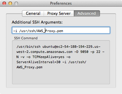
  • Click on the Advanced tab and in the Additional SSH Arguments field enter the following argument, this will tell Sidestep to use the SSH key and where to find it:  -i <path to your SSH key>/<SSH key>

    Sidestep AWS

  • Go back to the Proxy Server tab and click on Test Connection to Server. At this point your should see a “Connection succeeded!” message. 
  • Close the Preferences window now and click on Connect to get connected. If you open your browser now and search for “what is my IP”, your IP address will be the same as the EC2 instance IP address. From here Sidestep will automatically terminate the connection if you switch to a secure connection.

Note: if you decide to shut down your EC2 instance when you are not using it, please be aware that its public IP address and DNS name will be different after you turn it back on. That means you will need to update the hostname field in Sidestep every time you stop/start your instance. One way to work around that is to assign an Elastic IP (static) to your instance or install Linux dynamic update client on your Ubuntu.

Comment if you find this post useful.


Share This:
Facebooktwitterredditpinterestlinkedintumblrmail

How to Deploy Cisco Cloud Services Router (CSR) 1000v on Verizon Terremark Cloud

Note: This post is obselete. There is easier way now to install the Cisco CSR 1000v on Verizon Cloud. This link describes how to quickly spin up an instance.


The Cisco Cloud Services Router (CSR) 1000v is Cisco’s first virtual router and it runs as a VM on x86 virtualized server. The CSR 1000v runs Cisco IOS XE and brings many benefits to a cloud environment where it can operate as a secure VPN gateway to terminate site-to-site IPSEC tunnels. Other use cases of the CSR 1000v include MPLS WAN termination and control & traffic redirection. You can find more information n this virtual router on the Cisco CSR 1000v page.


In this post I’m going to show you how to install the CSR 1000v on the Verizon Terremark eCloud. If you are not familiar with the Verizon Terremark cloud console, you can go here for some video tutorials.


Download A Free Trial Image

  •  Go to the Cisco Download Center and log in using your Cisco credential. Select the latest software release from the left pane and then download the .iso package from the right pane to your desktop. Don’t download the OVA or BIN packages. This free trial should be good up to 6 months.  

Cisco CSR download

  • You can purchase a license from Cisco and upgrade to a full version after you install the CSR.

Create the VM


  • Go over to the Verizon Terremark Enterprise Cloud (eClould) page and log in using your credential.
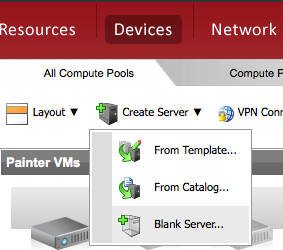
  • The first step here is to create a blank server. A blank server is just a container inside the VMware environment that will hold the Cisco IOS later. So go to Devices -> Create Server -> Blank Server to launch the wizard. 

Create Blank Server

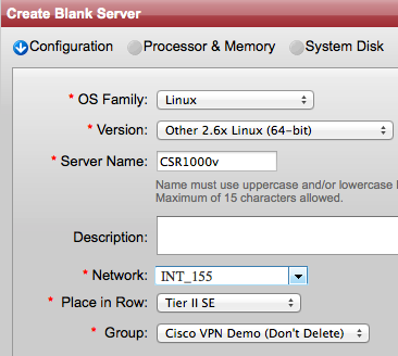
  • On the next screen select Linux for the OS Family, Other 2.6x Linux (64-bit) for the Version. Give the server a name and a description (optional). Then choose an INT network and  choose in which Row and Group you want to place the router. 

 Create blank server

  • On the next screen choose 4 or more for the Processors and 4096 MB or more for Memory. 

Choose VCPU and Memory

  • On the next screen enter 8 for the Disk size or choose a Detached Disk that’s at least 8GB. Click Next.
  • From the next window you can optionally assign tags or just click Next if you don’t want any tag.
  • On the next window review your configurations, check the Agreement box, and click Deploy. Give it about 2 minutes and the server should be ready. If you go to the row and group where you placed the router you should see a greyed out icon (powered off) there. 
  • If you recall we attached only one network to the server earlier, however the CSR requires a minimum of 3 interfaces to run so next we are going to create two additional networks and attach them to the blank server. Right click on the server and go to Configure to launch the wizard.
  • On the next screen choose Configure the Server and click Next.
  • On the next screen click on Network Settings from the top. At this point you should see only one INT network under the Current Connection. Click Add a Connection from the top right to add a new DMZ Network
  • Go click again on Add a Connection and this time choose an INT network (INT_XXX). Choose a unique INT network different from the one you have used when you created the blank server. Click Save.

Create additional vNICs

Now the VM will take a minute or so to reconfigure itself. 

  • Once the wheel stops spinning and VM is ready, right click on it and go to Power On. Powering on this VM should take a minute or so and while the machine is powering on an icon with gear spinning is presented. The greyed out icon should turn into an icon with “blue light” once the server is completely powered on.
 
Console to the VM
 
In order to console to the blank server you must VPN first and use the VMware remote console plugin in Firefox or Internet Explorer to connect to the server for the first time. So for the following steps make sure you are using either Firefox or IE. Once the CSR is up and running you can switch back to your favorite browser or use a Telnet/SSH client to connect it directly instead of using the console.
 
  • Click on the VPN Connect link from the top of the page. This will install the Cisco AnyConnect Mobility Client on your machine if you don’t already have it and connect you via secure SSL VPN to eClould. If the browser prompts you to install any Java or ActiveX plugin during this step make sure to accept. 

VPN Connect

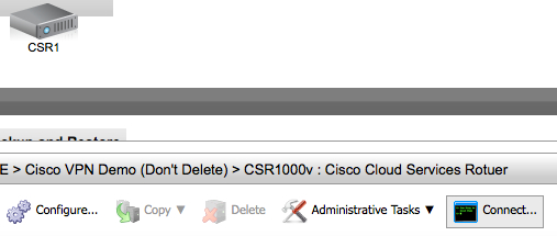
  • Now click on the router icon and then click on Connect from the bottom pane. This will start installing the VMware remote console plugin if it’s not already installed on your machine and will connect you to the server console to install the CSR. Console Connect
  • By now you should see “Operating system not found” message on the console screen. Go to Devices-> CD/DVD drive -> Connect to Disk Image File ISO. This will open a new window for you to locate the ISO package.  Cisco CSR connect to ISO3 
  • Select the ISO package from your local machine and click OK. The system will start uncompressing/unzipping the package and installing software. Depending on the file size and your network speed this process may take up to 2 or 3 hours. Come back in 3 hours to check on the install process. If the console session times out, reconnect again as you did previously.
  •  Once the CSR is successfully installed, you should see the traditional Cisco router prompt and you can then log in and start configuring it. 
Assigning IP Addresses
 
In this section we will assign IP addresses to the CSR 1000v interfaces. When we created the VM we added 3 interfaces for the CSR 1000v to use (INT_XXX, DMZ_XXX, and INT_XXX). Each CSR interface will map to a logical vNIC assigned by the VMware hypervisor. The vNIC in turn is mapped to a physical MAC address.
 
The following steps are very important and you should not begin configuring any features on the CSR 1000v before you execute all of them.
 
  • First we need to find the CSR interface to vNIC mappings so go ahead and create the following table on a piece of paper. You will be populating its fields along the way:
    NIC IDNetworkMACCSR InterfaceIP/MaskDefault Gateway
    1 (eth0)INT
    2 (eth1)DMZ
    3 (eth2)INT
  • Log in to the CSR console and issue the following command:

    show platform software vnic-if interface-mapping

    Csr in mapping
    You should see three interfaces with their vNIC and MAC addresses mapping. If you are running IOS XE 3.10S or earlier the first interface from the top should be GigabitEthernet0 and it’s the management interface. On the other hand if you are running 3.11S or higher the first interface is usually GigabitEthernet1. Start populating the table you have created n the previous step with the information from the command you just executed (IP information will come in the next steps) .

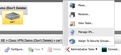
  • Go back to the eClould portal, click on the router and go then to Administrative Tasks -> Manage PIs
    Manage IPs
  • From the Networks section, click on the drop-down menu and select your DMZ network. Then from the left pane Available IPs select one IP address and click on the right green arrow to assign it to the server. Click Save.
  • Repeat the previous step to assign IP addresses for the INT (internal) interfaces.
  • Go back to the table and fill out the IP addresses, mask, gateway sections before you move on.
  • Now that you have the IP addresses, masks, and interface mappings start configuring the DMZ and INT interfaces of the CSR by issuing the following commands for each interface:

    config t
    int gX
    ip add <ip> <mask>
    description <Outside or LAN interface> 

Configure A Default Route
 
  • The final step here is to assign a default route so that the CSR can reach the internet. The CSR must use the DMZ default gateway to reach the internet because only the DMZ network can reach the internet because the INT networks are not visible from the outside. So copy from the table you have created the default gateway IP address for the DMZ network.
  • Go back to the CSR console and issue the following commands. Make sure that you replace the text in italic with the IP address of the default gateway
          config t
          ip route 0.0.0.0 0.0.0.0 <DMZ_Default_gateway>
          end
          write mem 
 
  • Try now pining the default gateway, you should get a response:
          ping <DMZ_default_gateway>
 
  • At this point, the CSR should be able to reach the internet. Issue the following ping to make sure:

    ping 8.8.8.8

    If you don’t get a response then something is wrong and you should revisit the previous steps.


Share This:
Facebooktwitterredditpinterestlinkedintumblrmail

Private VLAN and How It Affects Virtual Machine Communication

Private VLAN (PVLAN) is a security feature which has been available for quite some time on most modern switches. It adds a layer of security and enables network admins to restrict communication between servers in the same network segment (VLAN). So for example let’s say you have an Email and Web servers in the DMZ in the same VLAN and you don’t want them to communicate with each other but still want each server to communicate with the outside world. Obviously one way to prevent the servers from talking directly to each other is to place each server in a separate VLAN and apply ACLs on the firewall/router preventing communication between the two VLANs. This solution though requires using multiple VLANs and IP subnets. It also requires you to re-IP the servers in an existing environment. But what if you are running out of VLANs or IP subnets and/or re-IPing is too disruptive? Well then you can use PVLAN instead.

With PVLAN you can provide network isolation between servers or VMs which are in the same VLAN without introducing any additional VLANs or having to use MAC access control on the switch itself. 

While you can configure PVLAN on any modern physical switch, this post will focus on deploying PVLAN on a virtual distributed switch in a VMware vSphere environment.  

Private VLAN and Vmware vSphere

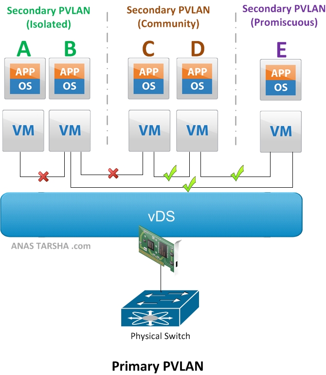
But first let me explain briefly how PVLAN works. The basic concept behind Private VLAN (PVLAN) is to divide up the existing VLAN (now referred to as Primary PVLAN) into multiple segments , called secondary PVLANs. Each Secondary PVLAN type then can be one of the following:

  • Promiscuous: VMs in this PVLAN can talk to any other VMs in the same Promiscuous PVLAN or any other secondary PVLANs. On the diagram above, VM E can communicate with A, B, C, and D.
  • Community: VMs in this secondary PVLAN can communicate with any VM in the same Community PVLAN and it can communicate with the Promiscuous PVLAN as explained above. However VMs in this PVLAN cannot talk to the Isolated PVLAN. So on the diagram, VM C and D can communicate with each other and communicate also with E.
  • Isolated: A VM in this secondary PVLAN cannot communicate with any VM in the same Isolated PVLAN nor with any VM in the Community PVLAN. It can only communicate with the Promiscuous PVLAN. So looking at the diagram again, VM A and B cannot communicate with each other nor with C or D but can communicate with E.

There are few things you need to be aware of when deploying PVLAN in a VMware vSphere environment,:

  • PVLAN is supported only on distributed virtual switches with Enterprise Plus license. PVLAN is not supported on a standard vSwitch.
  • PVLAN is supported on vDS in vSphere 4.0 or later; or on Cisco Nexus 1000v version 1.2 or later.
  • All traffic between VMs in the same PVLAN on different ESXi hosts need to traverse the upstream physical switch. So the upstream physical switch must be PVLAN-aware and configured accordingly. Note that this required only if you are deploying PVLAN on s vSphere vDS since VMware applies PVLAN enforcement at the destination while Cisco Nexus 1000v applies enforcement at the source and therefore allowing PVLAN support without upstream switch awareness.
Next I’m going to demonstrate how to configure PVLAN on VMware vDS and Cisco Nexus 1000v. Stay tuned for that. In the meantime feel free to leave some comments below.


Share This:
Facebooktwitterredditpinterestlinkedintumblrmail
Newer posts »